STOP AND START SYSTEM, Diagnostic DTC:P1780
| DTC Code | DTC Name |
|---|---|
| P1780 | Park / Neutral Position Switch Malfunction |
DESCRIPTION
The engine stop and start ECU detects malfunctions by comparing the conditions of the shift position signal and NSW signal. If a malfunction is detected, the engine stop and start ECU blinks the stop and start cancel indicator, prohibits stop and start control and stores DTC P1780.
| DTC No. | Freeze Frame Data * | DTC Detection Condition | Trouble Area |
|---|---|---|---|
| P1780 | Neutral Switch Stuck ON | Both of the following conditions are met for 2 seconds or more (2 trip detection logic):
Both of the following conditions are met for 2 seconds or more (2 trip detection logic):
|
|
| Neutral Switch Stuck OFF | Both of the following conditions are met for 15 seconds or more (2 trip detection logic):
|
|
*: Since each information can be confirmed by freeze frame data, record the freeze frame data before deleting the diagnosis code.
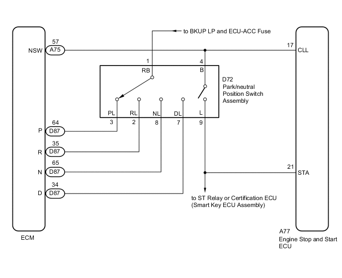
WIRING DIAGRAM
CAUTION / NOTICE / HINT
Note
-
Before replacing the engine stop and start ECU, read the number of starter operations and write it into a new engine stop and start ECU Click here.
-
After replacing the engine stop and start ECU or air conditioning amplifier assembly, reset and perform learning of the air conditioning information in the engine stop and start ECU Click here.
-
After replacing the engine stop and start ECU or airbag sensor assembly, clear and calibrate the deceleration sensor zero point in the engine stop and start ECU Click here.
-
Inspect the fuses for circuits related to this system before performing the following inspection procedure.
Tech Tips
Using the GTS, read the freeze frame data before troubleshooting. System condition information is recorded as freeze frame data the moment a DTC is stored. This information can be useful when troubleshooting Click here.
PROCEDURE
-
READ VALUE USING GTS (SHIFT SW STATUS)
-
Connect the GTS to the DLC3.
-
Turn the engine switch on (IG).
-
Turn the GTS on.
-
Enter the following menus: Powertrain / Transmission / Data List.
-
In accordance with the display on the GTS, read the Data List.
GTS Display Measurement Item / Range Normal Condition Diagnostic Note Shift SW Status (P Range) Park/neutral position switch assembly status /
ON or OFF
-
ON: Shift lever in P
-
OFF: Shift lever not in P
- Shift SW Status (R Range) Park/neutral position switch assembly status /
ON or OFF
-
ON: Shift lever in R
-
OFF: Shift lever not in R
- Shift SW Status (N Range) Park/neutral position switch assembly status /
ON or OFF
-
ON: Shift lever in N
-
OFF: Shift lever not in N
- Shift SW Status (D Range) Park/neutral position switch assembly status /
ON or OFF
-
ON: Shift lever in D or S
-
OFF: Shift lever not in D or S
- Result Result Proceed to Data display is within Normal Condition range A Data display is not within Normal Condition range B -
B 
INSPECT PARK/NEUTRAL POSITION SWITCH ASSEMBLY Click here
A 
-
-
READ VALUE USING GTS (NEUTRAL POSITION SW SIGNAL)
-
Enter the following menus: Powertrain / Transmission / Data List / Neutral Position SW Signal.
-
In accordance with the display on the GTS, read the Data List.
Tester Display Measurement Item / Range Normal Condition Diagnostic Note Neutral Position SW Signal Park/neutral position switch assembly status /
ON or OFF
-
ON: Shift lever in P or N
-
OFF: Shift lever not in P or N
- Result Result Proceed to Data display is not within Normal Condition range A Data display is within Normal Condition range B -
B 
USE SIMULATION METHOD TO CHECK Click here
A
-
-
INSPECT PARK/NEUTRAL POSITION SWITCH ASSEMBLY
-
Inspect the park/neutral position switch assembly Click here.
NG
REPLACE PARK/NEUTRAL POSITION SWITCH ASSEMBLY Click here
OK
-
-
CHECK HARNESS AND CONNECTOR (ENGINE STOP AND START ECU - PARK/NEUTRAL POSITION SWITCH ASSEMBLY)
-
Disconnect the A77 engine stop and start ECU connector.
-
Disconnect the D72 park/neutral position switch assembly connector.
-
Disconnect the A75 and D87 ECM connectors.
-
Disconnect the A36 certification ECU (smart key ECU assembly) connector.
-
Remove the ST relay from engine room relay block and junction block assembly.
-
Measure the resistance according to the value(s) in the table below.
Standard Resistance Tester Connection Condition Specified Condition A77-21 (STA) - D72-9 (L) Always Below 1 Ω A77-17 (CLL) - D72-4 (B) Always Below 1 Ω A77-21 (STA) or D72-9 (L) - Body ground Always 10 kΩ or higher A77-17 (CLL) or D72-4 (B) - Body ground Always 10 kΩ or higher
OK
REPLACE ENGINE STOP AND START ECU Click here
NG
REPAIR OR REPLACE HARNESS OR CONNECTOR
-
-
INSPECT PARK/NEUTRAL POSITION SWITCH ASSEMBLY
-
Inspect the park/neutral position switch assembly Click here.
NG
REPLACE PARK/NEUTRAL POSITION SWITCH ASSEMBLY Click here
OK
-
-
CHECK HARNESS AND CONNECTOR (ECM - PARK/NEUTRAL POSITION SWITCH ASSEMBLY)
-
Disconnect the A77 engine stop and start ECU connector.
-
Disconnect the D72 park/neutral position switch assembly connector.
-
Disconnect the A75 and D87 ECM connectors.
-
Disconnect the A36 certification ECU (smart key ECU assembly) connector.
-
Remove the ST relay from engine room relay block and junction block assembly.
-
Measure the resistance according to the value(s) in the table below.
Standard Resistance Tester Connection Condition Specified Condition D87-64 (P) - D72-3 (PL) Always Below 1 Ω D87-35 (R) - D72-2 (RL) Always Below 1 Ω D87-65 (N) - D72-8 (NL) Always Below 1 Ω D87-34 (D) - D72-7 (DL) Always Below 1 Ω A75-57 (NSW) - D72-4 (B) Always Below 1 Ω D87-64 (P) or D72-3 (PL) - Body ground Always 10 kΩ or higher D87-35 (R) or D72-2 (RL) - Body ground Always 10 kΩ or higher D87-65 (N) or D72-8 (NL) - Body ground Always 10 kΩ or higher D87-34 (D) or D72-7 (DL) - Body ground Always 10 kΩ or higher A77-17 (CLL), D72-4 (B) or A75-57 (NSW) - Body ground Always 10 kΩ or higher
OK
REPLACE ECM Click here
NG
REPAIR OR REPLACE HARNESS OR CONNECTOR
-