INTAKE MANIFOLD INSTALLATION
PROCEDURE
-
INSTALL INTAKE MANIFOLD
-
Install the wire harness clamp bracket to the intake manifold with the bolt.
- Torque:
- 10 N*m { 102 kgf*cm, 7 ft.*lbf }
-
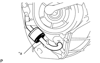
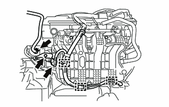
Text in Illustration *a Black Connect the 2 vacuum hoses to the intake manifold to install the No. 1 check valve.
Tech Tips
Check that the No. 1 check valve is installed as shown in the illustration.
-
Check the tumble control valves (w/ TCV).
Note
The tumble control valves may be damaged if they are not closed before installing the intake manifold.
Tech Tips
Connect the battery to the terminals of the intake air control valve actuator to operate the motor and close the tumble control valves Click here.
-
Install a new intake manifold gasket to the intake manifold.
-
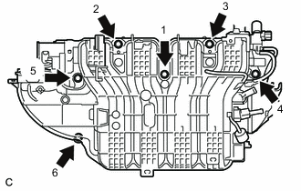
Install the intake manifold by tightening the 6 bolts in the sequence shown in the illustration (w/ TCV).
- Torque:
- 28 N*m { 286 kgf*cm, 21 ft.*lbf }
-
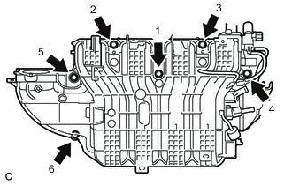
Install the intake manifold by tightening the 6 bolts in the sequence shown in the illustration (w/o TCV).
- Torque:
- 28 N*m { 286 kgf*cm, 21 ft.*lbf }
-
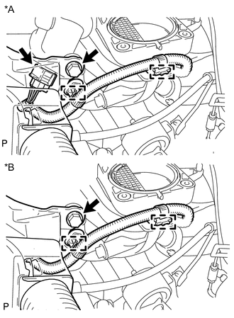
Text in Illustration *A w/ TCV *B w/o TCV Connect the intake air control valve actuator connector and engage the 2 wire harness clamps (w/ TCV).
-
Engage the 2 wire harness clamps (w/o TCV).
-
Install the wire harness with the bolt.
- Torque:
- 8.0 N*m { 82 kgf*cm, 71 in.*lbf }
-
Install the wire harness clamp bracket to the intake manifold with the bolt.
- Torque:
- 10 N*m { 102 kgf*cm, 7 ft.*lbf }
-
Connect the wire harness connector.
-
Engage the 3 wire harness clamps.
-
Connect the fuel vapor feed hose to the intake manifold and slide the clip to secure it.
-
Install the 2 wire harness clamp brackets to the intake manifold with the 2 bolts.
- Torque:
- 10 N*m { 102 kgf*cm, 7 ft.*lbf }
-
-
INSTALL FUEL DELIVERY PIPE
-
CONNECT FUEL TUBE SUB-ASSEMBLY
-
CONNECT UNION TO VACUUM TUBE HOSE (for LHD)
-
Connect the union to vacuum tube hose to the intake manifold and slide the clip to secure it.
-
-
CONNECT UNION TO CHECK VALVE HOSE (for RHD)
-
Connect the union to check valve hose to the intake manifold and slide the clip to secure it.
-
-
CONNECT NO. 2 VENTILATION HOSE
-
Connect the No. 2 ventilation hose to the intake manifold and slide the clip to secure it.
-
-
INSTALL VACUUM SWITCHING VALVE ASSEMBLY (for ACIS)
-
Install the vacuum switching valve assembly to the intake manifold with the bolt.
- Torque:
- 9.0 N*m { 92 kgf*cm, 80 in.*lbf }
-
Connect the 2 vacuum hoses and vacuum switching valve assembly connector.
-
for LHD:
-
Engage the wire harness clamp.
-
Connect the union to vacuum tube hose.
-
-
for RHD:
-
Engage the wire harness clamp.
-
Connect the union to check valve hose.
-
-
-
INSTALL THROTTLE WITH MOTOR BODY ASSEMBLY
-
INSTALL FRONT OUTER COWL TOP PANEL SUB-ASSEMBLY (for LHD)
-
INSTALL FRONT OUTER COWL TOP PANEL SUB-ASSEMBLY (for RHD)
-
INSTALL WINDSHIELD WIPER MOTOR AND LINK ASSEMBLY
-
CONNECT CABLE FROM NEGATIVE BATTERY TERMINAL
-
INSPECT FOR FUEL LEAK