FUEL PUMP(for High Pressure) INSTALLATION
PROCEDURE
-
TEMPORARILY INSTALL FUEL PUMP WITH SEAL SUB-ASSEMBLY
-
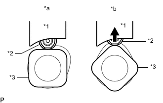
Text in Illustration *1 Fuel Pump Lifter Guide *2 Fuel Pump Lifter Assembly *3 Camshaft *a Correct *b Incorrect Turn the crankshaft pulley until the flat of the camshaft faces the fuel pump lifter assembly.
Tech Tips
This prevent the camshaft nose from pushing up the fuel pump lifter assembly when installing the fuel pump with seal sub-assembly.
-
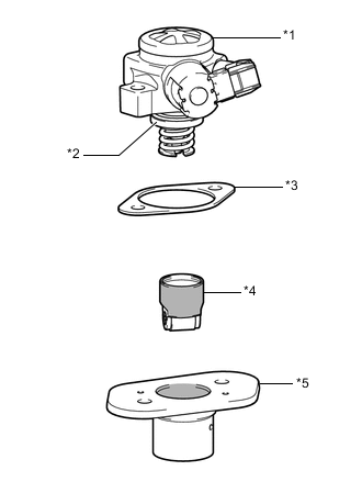
Text in Illustration *1 Fuel Pump with Seal Sub-assembly *2 O-ring *3 Fuel Pump Insulator *4 Fuel Pump Lifter Assembly *5 Fuel Pump Lifter Guide 
Engine Oil Application Area Apply engine oil to a new O-ring and install it to the fuel pump sub-assembly.
-
Apply engine oil to the inside of the fuel pump lifter guide and the outside of the fuel pump lifter assembly.
-
Install the fuel pump lifter assembly to the fuel pump lifter guide.
-
Install the fuel pump insulator to the fuel pump lifter guide.
-
Install the fuel pump with seal sub-assembly to the fuel pump lifter guide.
-
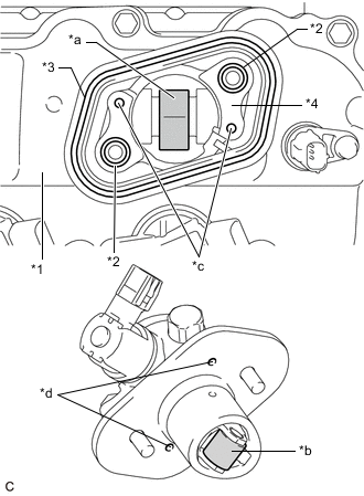
Text in Illustration *1 Cylinder Head Cover Sub-assembly *2 O-ring *3 Fuel Pump Spacer Gasket *4 No. 4 Camshaft Bearing Cap *a Pump Drive Cam (Engine Oil Application Area) *b Pump Lifter (Engine Oil Application Area) *c Knock Pin *d Pin Hole Apply 30 cc (1.8 cu. in.) of engine oil to the pump drive cam.
-
Apply engine oil to the fuel pump lifter assembly.
-
Apply engine oil to 2 new O-rings and install them to the No. 4 camshaft bearing cap.
-
Install a new fuel pump spacer gasket to the cylinder head cover sub-assembly.
-
Set the fuel pump with seal sub-assembly on the cylinder head cover sub-assembly.
-
Temporarily install the fuel pump with seal sub-assembly with the 2 bolts, leaving some allowance for left and right movement.
-
-
TEMPORARILY INSTALL NO. 1 FUEL PIPE SUB-ASSEMBLY
-
Connect the No. 1 fuel pipe sub-assembly to the fuel delivery pipe sub-assembly and tighten the union nut by hand.
-
Connect the No. 1 fuel pipe sub-assembly to the fuel pump with seal sub-assembly and tighten the union nut by hand.
Note
Do not damage the seals of the union nuts of the No. 1 fuel pipe sub-assembly when installing.
-
-
INSTALL FUEL PUMP WITH SEAL SUB-ASSEMBLY
Tech Tips
Perform "Inspection After Repair" after replacing the fuel pump with seal sub-assembly Click here.
-
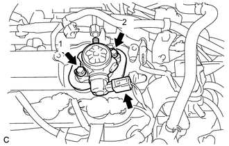
Tighten the 2 bolts in the order shown in the illustration.
- Torque:
- 30 N*m { 306 kgf*cm, 22 ft.*lbf }
-
Connect the fuel pump with seal sub-assembly connector.
-
-
INSTALL NO. 1 FUEL PIPE SUB-ASSEMBLY
-
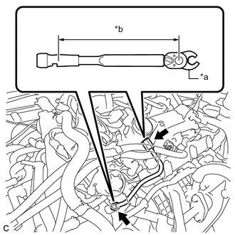
Text in Illustration *a 17 mm Union Nut Wrench *b Torque Wrench Fulcrum Length Using a 17 mm union nut wrench, tighten the union nut on the fuel pump with seal sub-assembly side of the No. 1 fuel pipe sub-assembly.
- Torque:
- 35 N*m { 357 kgf*cm, 26 ft.*lbf }
Tech Tips
-
Calculate the torque wrench reading when changing the fulcrum length of the torque wrench Click here.
-
When using a 17 mm union nut wrench (fulcrum length of 30 mm (1.18 in.)) + torque wrench (fulcrum length of 180 mm (7.09 in.)): 30 N*m (306 kgf*cm, 22 ft.*lbf)
-
Using a 17 mm union nut wrench, tighten the union nut on the fuel delivery pipe sub-assembly side of the No. 1 fuel pipe sub-assembly.
- Torque:
- 35 N*m { 357 kgf*cm, 26 ft.*lbf }
Tech Tips
-
Calculate the torque wrench reading when changing the fulcrum length of the torque wrench Click here.
-
When using a 17 mm union nut wrench (fulcrum length of 30 mm (1.18 in.)) + torque wrench (fulcrum length of 180 mm (7.09 in.)): 30 N*m (306 kgf*cm, 22 ft.*lbf)
-
-
INSTALL NO. 1 FUEL PIPE
-
Install the No. 1 fuel pipe and a new gasket to the fuel pump with seal sub-assembly.
- Torque:
- 40 N*m { 408 kgf*cm, 30 ft.*lbf }
-
-
CONNECT FUEL TUBE SUB-ASSEMBLY
-
Connect the fuel tube sub-assembly to the No. 1 fuel pipe.
-
-
INSTALL FUEL PUMP PROTECTOR
-
Install the fuel pump protector to the cylinder head cover sub-assembly with the 2 bolts.
- Torque:
- 21 N*m { 214 kgf*cm, 15 ft.*lbf }
-
-
INSTALL AIR CLEANER CASE SUB-ASSEMBLY
-
INSTALL AIR CLEANER FILTER ELEMENT SUB-ASSEMBLY
-
INSTALL INLET AIR CLEANER ASSEMBLY
-
INSTALL COOL AIR INTAKE DUCT SEAL
-
INSTALL THROTTLE BODY WITH MOTOR ASSEMBLY
-
CONNECT CABLE TO NEGATIVE BATTERY TERMINAL
Note
When disconnecting the cable, some systems need to be initialized after the cable is reconnected Click here.
-
INSPECT FOR FUEL LEAK
-
PERFORM INITIALIZATION
-
Perform "Inspection After Repair" after replacing the fuel pump with seal sub-assembly Click here.
-