FUEL INJECTOR INSTALLATION

PROCEDURE
-
INSTALL FUEL INJECTOR ASSEMBLY
Tech Tips
Perform "Inspection After Repair" after replacing a fuel injector assembly Click here.
-
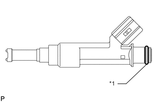
Text in Illustration *1 O-ring Apply a light coat of gasoline or spindle oil to new O-rings, and then install one onto each fuel injector assembly.
-
Apply a light coat of gasoline or spindle oil where the fuel delivery pipe contacts each O-ring.
-
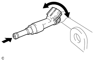
While turning the fuel injector assembly left and right, install it to the fuel delivery pipe.
Note
-
Do not damage the fuel injector assembly and O-ring.
-
Do not twist the O-ring.
-
After installing each fuel injector assembly, check that it turns smoothly. If not, replace the O-ring with a new one.
Tech Tips
Use the same procedure to install the other fuel injector assemblies.
-
-
-
INSTALL FUEL DELIVERY PIPE
-
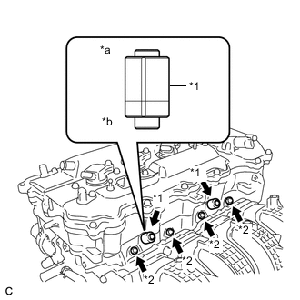
Text in Illustration *1 Fuel Delivery Spacer *2 Injector Vibration Insulator *a Fuel Delivery Pipe Side *b Cylinder Head Side Install 4 new injector vibration insulators to the cylinder head.
-
Install the 2 fuel delivery spacers onto the cylinder head.
Tech Tips
Install the fuel delivery spacer so that the longer protrusion is on the cylinder head side.
-
Install the fuel delivery pipe with the 4 fuel injector assemblies and install the 2 bolts.
- Torque:
- 21 N*m { 214 kgf*cm, 15 ft.*lbf }
Note
-
Do not drop the fuel injector assemblies when installing the fuel delivery pipe.
-
Check that the fuel injector assemblies rotate smoothly after installing the fuel delivery pipe.
-
-
CONNECT WIRE HARNESS
-
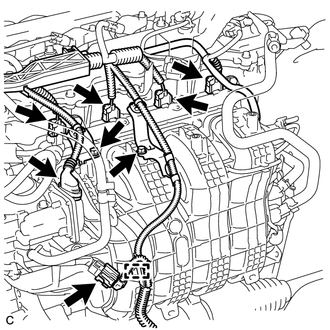
Engage the clamp to connect the wire harness.
-
Install the 2 wire harness brackets to the intake manifold with the 2 bolts.
- Torque:
- 10 N*m { 102 kgf*cm, 7 ft.*lbf }
-
Connect the 4 fuel injector assembly connectors, throttle body with motor assembly connector and sensor wire connector.
-
-
INSTALL VACUUM SWITCHING VALVE ASSEMBLY (for ACIS)
-
CONNECT FUEL TUBE SUB-ASSEMBLY
-
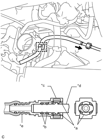
Text in Illustration *a Retainer *b O-ring *c Fuel Tube Connector *d Fuel Pipe *e Nylon Tube Connect the fuel tube sub-assembly to the fuel pipe.
Note
Check if there is any damage or foreign matter on the connecting parts of the fuel lines.
-
Align the fuel tube connector with the fuel pipe, and push them together until the fuel tube connector makes a "click" sound. If it is difficult to push the fuel pipe into the fuel tube connector, apply a small amount of clean engine oil to the tip of the fuel pipe and reinsert it.
-
After connecting the fuel lines, check that the fuel pipe and fuel tube connector are securely connected by pulling on them.
-
-
Engage the claw and install the No. 1 fuel pipe clamp.
-
Engage the clamp to connect the fuel tube sub-assembly to the fuel hose clamp.
-
-
INSTALL AIR CLEANER CAP SUB-ASSEMBLY
-
CONNECT CABLE TO NEGATIVE BATTERY TERMINAL
Note
When disconnecting the cable, some systems need to be initialized after the cable is reconnected Click here.
-
INSPECT FOR FUEL LEAK
-
INSTALL NO. 1 ENGINE COVER SUB-ASSEMBLY