ENGINE ASSEMBLY INSTALLATION

CAUTION / NOTICE / HINT
Tech Tips
Perform "Inspection After Repair" after replacing the engine assembly Click here.
PROCEDURE
-
REMOVE ENGINE STAND
-
Using an engine sling device and engine lift, secure the engine assembly.
Note
-
Adjust the angle of the sling device carefully to prevent the engine assembly or engine hanger from deforming or becoming damaged.
-
Do not perform any procedures while the engine assembly is suspended because doing so may cause the engine assembly to drop, resulting in injury. However, the engine assembly needs to be suspended when it is installed or removed from an engine stand.
-
-
Remove the engine assembly from the engine stand.
-
-
INSTALL DRIVE PLATE AND RING GEAR SUB-ASSEMBLY
-
INSTALL AUTOMATIC TRANSAXLE ASSEMBLY
-
INSTALL ENGINE MOUNTING BRACKET RH
-
Install the engine mounting bracket RH with the 3 bolts.
- Torque:
- 54 N*m { 551 kgf*cm, 40 ft.*lbf }
-
-
INSTALL DRIVE SHAFT BEARING BRACKET
-
Install the drive shaft bearing bracket with the 3 bolts.
- Torque:
- 64 N*m { 653 kgf*cm, 47 ft.*lbf }
-
-
TEMPORARILY INSTALL FRONT ENGINE MOUNTING INSULATOR
-
Temporarily install the front engine mounting insulator with the 3 nuts.
Tech Tips
Perform this procedure only when replacement of the front engine mounting insulator is necessary.
-
-
TEMPORARILY INSTALL ENGINE MOUNTING INSULATOR LH
-
Temporarily install the engine mounting insulator LH with the 3 nuts.
Tech Tips
Perform this procedure only when replacement of the engine mounting insulator LH is necessary.
-
-
TEMPORARILY INSTALL ENGINE MOUNTING INSULATOR RH
-
Temporarily install the engine mounting insulator RH with the 3 nuts.
Tech Tips
Perform this procedure only when replacement of the engine mounting insulator RH is necessary.
-
-
INSTALL FRONT FRAME ASSEMBLY
-
Install the engine mounting insulator LH with the nut.
- Torque:
- 95 N*m { 969 kgf*cm, 70 ft.*lbf }
-
Install the engine mounting insulator RH with the nut.
- Torque:
- 95 N*m { 969 kgf*cm, 70 ft.*lbf }
-
Install the front engine mounting insulator with the bolt.
- Torque:
- 87 N*m { 887 kgf*cm, 64 ft.*lbf }
-
Fully tighten the 9 temporarily installed nuts of the engine mounting insulators to the specified torque.
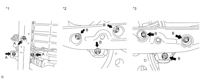
Text in Illustration *1 Front Engine Mounting Insulator *2 Engine Mounting Insulator RH *3 Engine Mounting Insulator LH - - Tech Tips
Perform this procedure only when replacement of the engine mounting insulator is necessary.
- Torque:
- A
- 58 N*m { 591 kgf*cm, 43 ft.*lbf }
- B
- 99 N*m { 1010 kgf*cm, 73 ft.*lbf }
-
Install the 4 hole plugs.
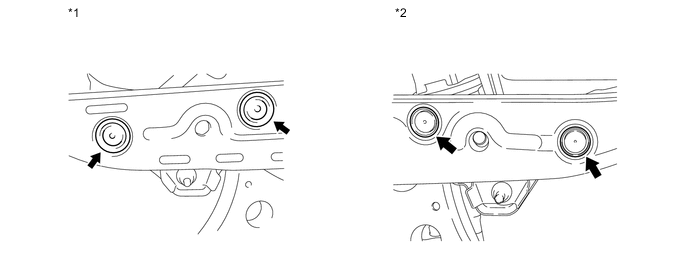
Text in Illustration *1 Engine Mounting Insulator RH *2 Engine Mounting Insulator LH Tech Tips
Perform this procedure only when replacement of the engine mounting insulator is necessary.
-
-
INSTALL GENERATOR ASSEMBLY
-
INSTALL COMPRESSOR ASSEMBLY WITH PULLEY
-
INSTALL V-RIBBED BELT
-
INSTALL ENGINE WIRE
-
Install the engine wire to the engine assembly with transaxle.
-
-
INSTALL ENGINE ASSEMBLY WITH TRANSAXLE
-
Set the engine assembly with transaxle on an engine lifter.
Note
-
Install height adjustment attachments and plate lift attachments under the engine assembly with transaxle.
-
To prevent the oil pan sub-assembly from deforming, do not place any attachments under the oil pan sub-assembly of the engine assembly with transaxle.
-
Make sure to support the engine assembly with transaxle securely to prevent it from falling.
-
-
Remove the engine hangers Click here.
-
Install the engine assembly with transaxle to the vehicle.
Note
Do not raise the engine assembly more than necessary. If the engine assembly is raised excessively, the vehicle may also be lifted up.
Tech Tips
-
Make sure that the engine assembly is clear of all wiring and hoses.
-
While raising the engine assembly with transaxle into the vehicle, do not allow it to contact the vehicle.
-
-
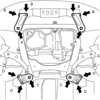
Install the frame side rail plate RH and frame side rail plate LH with the 4 bolts and 2 nuts.
- Torque:
- A
- 85 N*m { 867 kgf*cm, 63 ft.*lbf }
- B
- 64 N*m { 653 kgf*cm, 47 ft.*lbf }
-
Install the front suspension member brace rear RH and front suspension member brace rear LH with the 4 bolts and 2 nuts.
- Torque:
- C
- 85 N*m { 867 kgf*cm, 63 ft.*lbf }
- D
- 64 N*m { 653 kgf*cm, 47 ft.*lbf }
Tech Tips
Perform "Inspection After Repair" after replacing the engine assembly Click here.
-
-
INSTALL DRIVE PLATE AND TORQUE CONVERTER ASSEMBLY SETTING BOLT
-
INSTALL FLYWHEEL HOUSING UNDER COVER
-
Install the flywheel housing under cover.
-
-
CONNECT STEERING INTERMEDIATE SHAFT ASSEMBLY
-
INSTALL FRONT DRIVE SHAFT HOLE SNAP RING LH
-
INSTALL FRONT DRIVE SHAFT ASSEMBLY LH
-
INSTALL FRONT DRIVE SHAFT ASSEMBLY RH
-
CONNECT FRONT LOWER NO. 1 SUSPENSION ARM SUB-ASSEMBLY LH
-
CONNECT FRONT LOWER NO. 1 SUSPENSION ARM SUB-ASSEMBLY RH
Tech Tips
Use the same procedure described for the LH side.
-
CONNECT TIE ROD ASSEMBLY LH
-
CONNECT TIE ROD ASSEMBLY RH
Tech Tips
Use the same procedure described for the LH side.
-
INSTALL FRONT SPEED SENSOR LH
-
INSTALL FRONT SPEED SENSOR RH
Tech Tips
Use the same procedure described for the LH side.
-
INSTALL FRONT STABILIZER LINK ASSEMBLY LH
-
INSTALL FRONT STABILIZER LINK ASSEMBLY RH
Tech Tips
Use the same procedure described for the LH side.
-
INSTALL FRONT AXLE SHAFT NUT LH
-
INSTALL FRONT AXLE SHAFT NUT RH
Tech Tips
Use the same procedure described for the LH side.
-
INSTALL FRONT EXHAUST PIPE ASSEMBLY
-
CONNECT FUEL TUBE SUB-ASSEMBLY
-
CONNECT NO. 1 COOLER REFRIGERANT DISCHARGE HOSE
-
CONNECT NO. 1 COOLER REFRIGERANT SUCTION HOSE
-
CONNECT UNION TO VACUUM TUBE HOSE (for LHD)
-
Connect the union to vacuum tube hose and slide the clip to secure it.
-
-
CONNECT UNION TO CHECK VALVE HOSE (for RHD)
-
Connect the union to check valve hose and slide the clip to secure it.
-
-
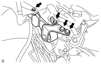
INSTALL ENGINE MOVING CONTROL ROD
-
Temporarily install the engine moving control rod and No. 3 engine mounting stay RH to the engine moving control rod bracket with the bolt.
Tech Tips
Perform this procedure only when replacement of the engine moving control rod is necessary.
-
-
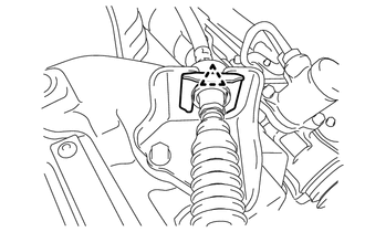
INSTALL ENGINE MOVING CONTROL ROD BRACKET
-
When the engine moving control rod has been replaced.
-
Temporarily install the engine moving control rod bracket with the 4 bolts.
-
Fully tighten the 4 bolts.
- Torque:
- 38 N*m { 387 kgf*cm, 28 ft.*lbf }
-
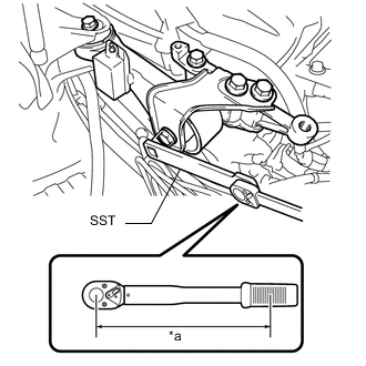
Text in Illustration *a Torque Wrench Fulcrum Length Using SST, fully tighten the bolt.
- SST
- 09961-00950
- Torque:
- Specified tightening torque
- 52 N*m { 530 kgf*cm, 38 ft.*lbf }
Note
-
Calculate the torque wrench reading when changing the fulcrum length of the torque wrench Click here.
-
When using SST (fulcrum length of 150 mm (5.91 in.)) + torque wrench (fulcrum length of 260 mm (10.2 in.)):
33 N*m (337 kgf*cm, 24 ft.*lbf)
-
-
When the engine moving control rod has been reused.
-
Temporarily install the engine moving control rod bracket with the 4 bolts.
-
Fully tighten the 4 bolts.
- Torque:
- 38 N*m { 387 kgf*cm, 28 ft.*lbf }
-
-
-
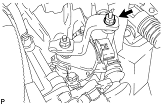
INSTALL EARTH WIRE
-
Install the earth wire to the engine moving control rod bracket with the bolt.
- Torque:
- 8.0 N*m { 82 kgf*cm, 71 in.*lbf }
-
-
INSTALL NO. 2 ENGINE MOUNTING STAY RH
-
Install the No. 2 engine mounting stay RH with the 2 bolts.
- Torque:
- 38 N*m { 387 kgf*cm, 28 ft.*lbf }
-
-
CONNECT TRANSMISSION CONTROL CABLE ASSEMBLY
-
Connect the transmission control cable assembly to the No. 1 control cable bracket with a new clip.
-
Install the transmission control cable assembly to the control shaft lever with the nut.
- Torque:
- 12 N*m { 122 kgf*cm, 9 ft.*lbf }
-
-
INSTALL NO. 1 AIR CLEANER BRACKET
-
Install the No. 1 air cleaner bracket to the battery carrier with the bolt.
- Torque:
- 8.0 N*m { 82 kgf*cm, 71 in.*lbf }
-
Connect the 2 wire clamps.
-
-
CONNECT ENGINE WIRE
-
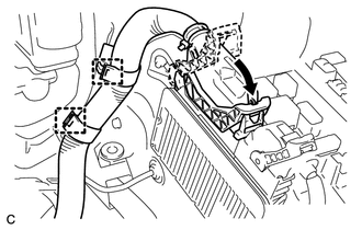
Connect the 2 wire clamps.
-
Connect the ECM connector with the lock lever.
-
Connect the engine wire to the engine room relay block.
-
Connect the 4 connectors.
-
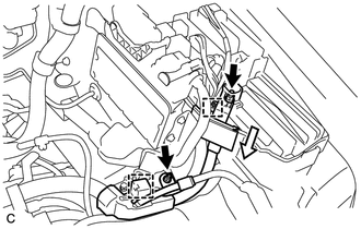
Connect the engine wire to the engine room relay block with the clamp.
-
Connect the wire clamp and install the 2 nuts.
- Torque:
- 8.0 N*m { 82 kgf*cm, 71 in.*lbf }
-
Install the No. 1 relay block cover.
-
-
INSTALL STARTER ASSEMBLY
-
CONNECT NO. 3 WATER BY-PASS HOSE
-
Connect the No. 3 water by-pass hose and slide the clip to secure it.
-
Connect the breather plug to the No. 3 water by-pass hose.
-
-
CONNECT NO. 4 WATER BY-PASS HOSE
-
Connect the No. 4 water by-pass hose and slide the clip to secure it.
-
-
CONNECT OUTLET HEATER WATER HOSE B
-
Connect the outlet heater water hose B and slide the clip to secure it.
-
Engage the 2 claws to connect the inlet heater water hose and outlet heater water hose A.
-
-
CONNECT INLET HEATER WATER HOSE
-
Connect the inlet heater water hose and slide the clip to secure it.
-
-
CONNECT NO. 1 RADIATOR HOSE
-
Connect the No. 1 radiator hose and slide the clip to secure it.
-
Connect the air fuel ratio sensor wire to the No. 1 radiator hose with the hose clamp.
-
-
CONNECT NO. 2 RADIATOR HOSE
-
Connect the No. 2 radiator hose and slide the clip to secure it.
-
-
INSTALL RADIATOR RESERVE TANK ASSEMBLY
-
INSTALL BATTERY
-
Install the battery and battery tray.
-
Install the battery clamp with the bolt and nut.
- Torque:
- Bolt
- 9.0 N*m { 92 kgf*cm, 80 in.*lbf }
- Nut
- 3.5 N*m { 36 kgf*cm, 31 in.*lbf }
-
Connect the cable to the positive (+) battery terminal
- Torque:
- 6.9 N*m { 70 kgf*cm, 61 in.*lbf }
-
-
INSTALL AIR CLEANER CASE SUB-ASSEMBLY
-
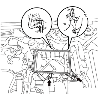
Text in Illustration *a Hole *b Projection Insert the projection of the air cleaner case sub-assembly into the hole of the No. 2 air cleaner bracket as shown in the illustration.
-
Install the 2 bolts.
- Torque:
- 5.0 N*m { 51 kgf*cm, 44 in.*lbf }
-
Connect the wire harness clamp.
-
-
INSTALL AIR CLEANER FILTER ELEMENT SUB-ASSEMBLY
-
Install the air cleaner filter element sub-assembly to the air cleaner case sub-assembly.
Note
Install the air cleaner filter element sub-assembly with the printed side facing the vehicle front.
-
-
INSTALL AIR CLEANER CAP SUB-ASSEMBLY
-
INSTALL INLET AIR CLEANER ASSEMBLY
-
Install the inlet air cleaner assembly with the 2 bolts.
- Torque:
- 8.0 N*m { 82 kgf*cm, 71 in.*lbf }
-
-
CONNECT CABLE TO NEGATIVE BATTERY TERMINAL
-
Connect the cable to the negative (-) battery terminal.
- Torque:
- 6.9 N*m { 70 kgf*cm, 61 in.*lbf }
Note
When disconnecting the cable, some systems need to be initialized after the cable is reconnected Click here.
-
-
ADD ENGINE OIL
-
ADD ENGINE COOLANT
-
ADD AUTOMATIC TRANSAXLE FLUID
-
CHARGE AIR CONDITIONING SYSTEM WITH REFRIGERANT
-
WARM UP ENGINE
-
INSPECT FOR FUEL LEAK
-
INSPECT FOR OIL LEAK
-
INSPECT FOR COOLANT LEAK
-
INSPECT FOR EXHAUST GAS LEAK
-
INSPECT FOR REFRIGERANT LEAK
-
INSPECT IGNITION TIMING
-
INSPECT ENGINE IDLE SPEED
-
INSPECT CO/HC
-
INSTALL NO. 1 ENGINE COVER SUB-ASSEMBLY
-
Engage the 3 pins to install the No. 1 engine cover sub-assembly.
-
-
INSTALL COOL AIR INTAKE DUCT SEAL
-
INSPECT AND ADJUST SHIFT LEVER POSITION
-
INSTALL FRONT FENDER APRON SEAL LH
-
Install the front fender apron seal LH with the 2 bolts and clip.
-
-
INSTALL FRONT FENDER APRON SEAL RH
-
Install the front fender apron seal RH with the 2 bolts and clip.
-
-
INSTALL ENGINE UNDER COVER LH
-
Install the engine under cover LH with the 2 screws and 2 clips.
-
-
INSTALL FRONT WHEEL OPENING EXTENSION PAD LH
-
Install the front wheel opening extension pad LH with the 3 screws.
-
-
INSTALL ENGINE UNDER COVER RH
-
Install the engine under cover RH with the 2 screws and 3 clips.
-
-
INSTALL FRONT WHEEL OPENING EXTENSION PAD RH
-
Install the front wheel opening extension pad RH with the 3 screws.
-
-
INSTALL FRONT WHEELS
- Torque:
- 103 N*m { 1049 kgf*cm, 76 ft.*lbf }
-
INSPECT AND ADJUST FRONT WHEEL ALIGNMENT
-
CHECK FOR SPEED SENSOR SIGNAL