BRAKE ACTUATOR(for LHD with Vacuum Brake Booster) REMOVAL
CAUTION / NOTICE / HINT
The necessary procedures (adjustment, calibration, initialization, or registration) that must be performed after parts are removed, installed, or replaced during brake actuator assembly removal/installation are shown below.
| Replaced Part or Performed Procedure | Necessary Procedure | Effect/Inoperative Function when Necessary Procedure not Performed | Link |
|---|---|---|---|
| Battery terminal is disconnected/reconnected | Drive the vehicle until stop and start control is permitted (approximately 5 to 60 minutes) | Stop and start system | for 8GR-FKS: Click here for V35A-FTS: Click here |
| Memorize steering angle neutral point | LKA/LDA system | ||
| Parking support brake system* | |||
| Pre-collision system | |||
| Adaptive high beam system | |||
Lighting system (EXT) |
|||
| Variable gear ratio steering system | |||
| Parking assist monitor system | |||
| Panoramic view monitor system | |||
| Initialize rear door sunshade system | Variable gear ratio steering system | ||
| Initialize power trunk lid system | Parking assist monitor system | ||
| Brake actuator assembly | Perform acceleration sensor (yaw rate sensor) zero point calibration and store system information |
|
Click here Click here
PROCEDURE
-
PRECAUTION
Note
After turning the engine switch off, waiting time may be required before disconnecting the cable from the negative (-) battery terminal. Therefore, make sure to read the disconnecting the cable from the negative (-) battery terminal notice before proceeding with work.
-
DISCONNECT CABLE FROM NEGATIVE BATTERY TERMINAL
Note
When disconnecting the cable, some systems need to be initialized after the cable is reconnected.
-
REMOVE UPPER RADIATOR SUPPORT SEAL
-
REMOVE FENDER APRON BRACE SUB-ASSEMBLY LH
-
DRAIN BRAKE FLUID
Note
Wash off brake fluid immediately if it comes in contact with any painted surface.
-
REMOVE COWL TOP VENTILATOR LOUVER SUB-ASSEMBLY
-
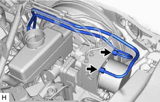
DISCONNECT UNION TO CHECK VALVE HOSE
-
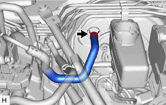
Slide the clip and disconnect the union to check valve hose from the brake booster assembly.
-
-
REMOVE BRAKE ACTUATOR ASSEMBLY WITH BRACKET
-
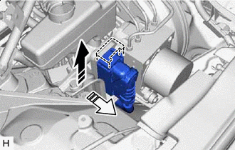

Lock Lever Released 
Connector Disconnected Release the lock lever and disconnect the wire harness connector from the brake actuator assembly.
Note
Be careful not to allow brake fluid to enter the removed wire harness connector.
-
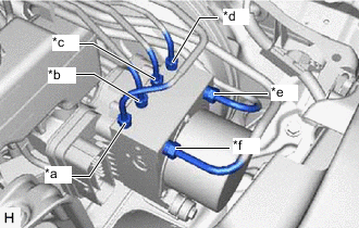
*a to Front Wheel Cylinder RH *b to Front Wheel Cylinder LH *c to Rear Wheel Cylinder RH *d to Rear Wheel Cylinder LH *e from Front Master Cylinder Port *f from Rear Master Cylinder Port Use tags or make a memo to identify the places to reconnect.
-
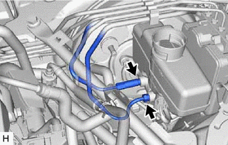
Using a union nut wrench, disconnect the 2 brake lines from the brake master cylinder sub-assembly.
-
Using a union nut wrench, disconnect the 2 brake lines from the brake actuator assembly.
-
Disconnect the clamp and remove the 2 brake lines.
-
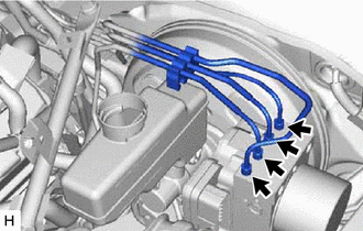
Using a union nut wrench, disconnect the 4 brake lines from the brake actuator assembly.
-
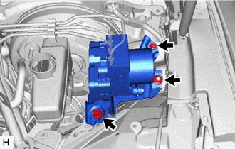
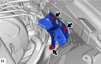
Remove the 2 bolts, nut and brake actuator assembly with bracket.
Note
Be careful not to damage the brake tubes.
-
-
REMOVE NO. 4 BRAKE ACTUATOR BRACKET
-
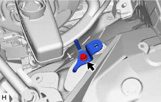
Remove the bolt and No. 4 brake actuator bracket.
-
-
REMOVE NO. 5 BRAKE ACTUATOR BRACKET
-
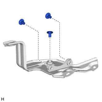
Remove the 3 bolts and No. 5 brake actuator bracket.
-
-
REMOVE BRAKE ACTUATOR BRACKET ASSEMBLY
-
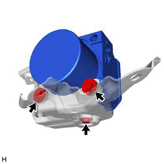
Remove the 3 bolts and brake actuator bracket assembly.
-
-
REMOVE NO. 1 BRAKE ACTUATOR CASE COLLAR
-
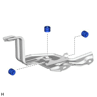
Remove the 3 No. 1 brake actuator case collars from the brake actuator bracket cushions.
-
-
REMOVE BRAKE ACTUATOR BRACKET CUSHION
-
Remove the 3 brake actuator bracket cushions from the brake actuator bracket assembly.
-