STEERING GEAR REMOVAL

CAUTION / NOTICE / HINT
Tech Tips
-
Use the same procedure for RHD and LHD vehicles.
-
The procedure listed below is for LHD vehicles.
PROCEDURE
-
PLACE FRONT WHEELS FACING STRAIGHT AHEAD
-
SECURE STEERING WHEEL
-
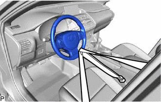
Secure the steering wheel assembly with the seat belt in order to prevent rotation.
Tech Tips
This operation is useful to prevent damage to the spiral cable.
-
-
REMOVE COLUMN HOLE COVER SILENCER SHEET
-
Fold back the floor carpet, and then remove the 2 clips and column hole cover silencer sheet.
-
-
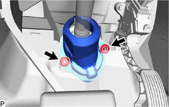
DISCONNECT NO. 2 STEERING INTERMEDIATE SHAFT ASSEMBLY
-
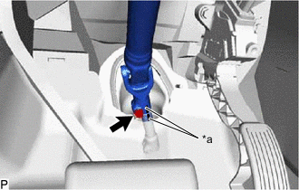
*a Matchmark Place matchmarks on the sliding yoke of the steering intermediate shaft.
-
Remove the bolt and disconnect the No. 2 steering intermediate shaft assembly.
-
-
DISCONNECT NO. 1 STEERING COLUMN HOLE COVER SUB-ASSEMBLY
-
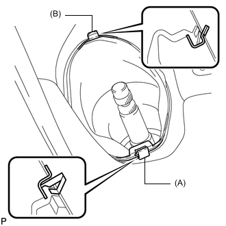
Remove the clip (A), disengage the clip (B) from the body and separate the No. 1 steering column hole cover sub-assembly.
Note
Do not damage the clips (A) and (B).
-
-
REMOVE FRONT WHEELS
-
REMOVE NO. 1 ENGINE UNDER COVER ASSEMBLY
-
REMOVE FRONT FLOOR COVER CENTER LH
-
REMOVE REAR ENGINE UNDER COVER LH
-
REMOVE REAR ENGINE UNDER COVER RH
-
DISCONNECT TIE ROD END SUB-ASSEMBLY LH
-
Remove the cotter pin and castle nut.
-
Using SST, disconnect the tie rod end sub-assembly LH from the steering knuckle.
- SST
- 09960-20010 ( 09961-02060 )
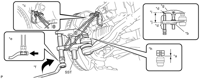
*a 1 mm (0.0397 in.) *b Nut *c String *d Molybdenum Grease Application Area *e Place the wrench here *f Turn *g SST Number *h Spacer B *i Body *j Claw CAUTION:
Apply molybdenum grease to the bolt threads and the tip of SST.
Note
-
Make sure to tie the string of SST to the vehicle to prevent SST from dropping.
-
As the ball joint dust cover may be damaged, adjust SST with the center nut so that the body and claw are parallel.
-
Do not damage the ball joint boot of the tie rod end.
-
Do not damage the steering knuckle.
-
Do not damage the front disc brake dust cover.
-
-
DISCONNECT TIE ROD END SUB-ASSEMBLY RH
Tech Tips
Use the same procedure described for the LH side.
-
DISCONNECT FRONT STABILIZER LINK ASSEMBLY LH
-
DISCONNECT FRONT STABILIZER LINK ASSEMBLY RH
Tech Tips
Use the same procedure described for the LH side.
-
REMOVE FRONT SUSPENSION MEMBER REINFORCEMENT LH
-
REMOVE FRONT SUSPENSION MEMBER REINFORCEMENT RH
Tech Tips
Use the same procedure described for the LH side.
-
REMOVE FRONT SUSPENSION MEMBER REAR BRACE LH
-
REMOVE FRONT SUSPENSION MEMBER REAR BRACE RH
Tech Tips
Use the same procedure described for the LH side.
-
REMOVE LOWER ENGINE FRONT MOUNTING BRACKET REINFORCEMENT (3ZR-FAE 2WD)
-
REMOVE FRONT SUSPENSION CROSSMEMBER SUB-ASSEMBLY
-
REMOVE NO. 1 STEERING COLUMN HOLE COVER SUB-ASSEMBLY
-
Remove the clamp.
-
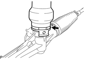
Remove the No. 1 steering column hole cover sub-assembly from the steering gear assembly.
-
-
REMOVE STEERING INTERMEDIATE SHAFT
-
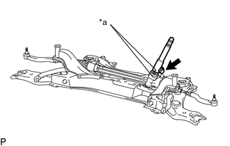
*a Matchmark Place matchmarks on the steering intermediate shaft and steering gear assembly.
-
Remove the bolt and steering intermediate shaft from the steering gear assembly.
-
-
REMOVE STEERING GEAR ASSEMBLY
-
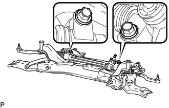
Remove the 2 bolts, 2 nuts and steering gear assembly from the front suspension crossmember sub-assembly.
Note
Because the nut has its own stopper, do not turn the nut. Loosen the bolt with the nut fixed in place.
-