BRAKE ACTUATOR(for LHD) INSTALLATION

CAUTION / NOTICE / HINT
Note
While the auxiliary battery is connected, even if the power switch is off, the brake control system activates when the brake pedal is depressed or any door courtesy switch is turned on. Therefore, when servicing brake system components, do not depress the brake pedal or open/close the doors while the auxiliary battery is connected.
PROCEDURE
-
INSTALL BRAKE ACTUATOR ASSEMBLY
-
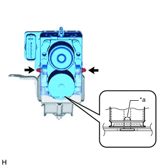
*a Pin Install the brake actuator assembly to the brake actuator bracket assembly with the 2 nuts.
- Torque:
- 5.4 N*m { 55 kgf*cm, 48 in.*lbf }
Note
-
Do not remove the hole plugs of a new brake actuator assembly before connecting the brake lines because the brake actuator assembly is filled with brake fluid.
-
Securely insert the pin of the brake actuator bracket assembly to the brake actuator assembly.
-
-
INSTALL BRAKE ACTUATOR WITH BRACKET
-
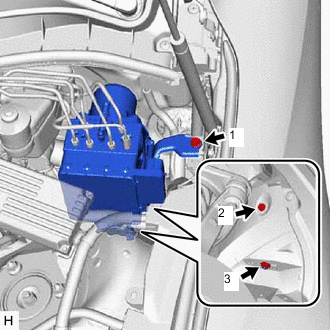
Temporarily install the brake actuator with bracket with the 2 bolts and nut.
Note
Do not kink or damage the brake lines.
Tech Tips
Install the brake actuator with bracket while avoiding the brake lines.
-
Fully tighten the 2 bolts and nut in the order shown in the illustration.
- Torque:
- 19 N*m { 194 kgf*cm, 14 ft.*lbf }
-
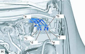
*a From Brake Master Cylinder Sub-assembly *b From Brake Stroke Simulator Cylinder Sub-assembly *c To Front Wheel Cylinder Assembly RH *d To Rear Wheel Cylinder Assembly LH *e To Rear Wheel Cylinder Assembly RH *f To Front Wheel Cylinder Assembly LH Temporarily tighten the 6 brake lines to the correct position on the brake actuator assembly as shown in the illustration.
-
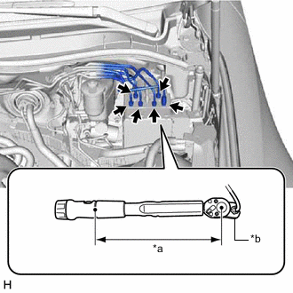
*a Torque Wrench Fulcrum Length *b Union Nut Wrench Using a union nut wrench, fully tighten the 6 brake lines.
- Torque:
- Specified tightening torque
- 15.2 N*m { 155 kgf*cm, 11 ft.*lbf }
Note
-
Do not kink or damage the brake lines.
-
Do not allow the brake lines to twist or interfere with other parts or vehicle body during tightening.
-
Do not allow any foreign matter such as dirt or dust to enter the brake lines from the connecting parts.
Tech Tips
-
Calculate the torque wrench reading when changing the fulcrum length of the torque wrench.
-
When using a union nut wrench (fulcrum length of 22 mm (0.866 in.)) + torque wrench (fulcrum length of 162 mm (6.38 in.)):
13.38 N*m (136 kgf*cm, 10 ft.*lbf)
-
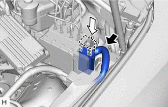

Connect the connector 
Lock the lock lever Connect the connector to the brake actuator assembly and lock the lock lever.
Note
-
Make sure that the connector is locked securely.
-
Make sure that the connector can be connected smoothly. Do not allow water, oil or dirt to enter the connector.
-
-
-
CONNECT NO. 1 RESERVOIR HOSE
-
Connect the No. 1 reservoir hose to the brake actuator assembly and slide the clip to secure it.
-
-
INSTALL SKID CONTROL ECU BRACKET ASSEMBLY
-
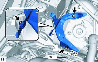
*a Claw Engage the claw.
-
Temporarily install the skid control ECU bracket assembly with the 3 bolts.
-
Fully tighten the 3 bolts in the order shown in the illustration.
- Torque:
- 8.5 N*m { 87 kgf*cm, 75 in.*lbf }
-
Engage the wire harness clamp to the skid control ECU bracket assembly.
-
-
INSTALL NO. 3 ENGINE ROOM RELAY BLOCK
-
Engage the claw to install the No. 3 engine room relay block to the skid control ECU bracket assembly.
-
-
INSTALL SKID CONTROL ECU ASSEMBLY
-
CONNECT CABLE TO NEGATIVE AUXILIARY BATTERY TERMINAL
Note
When disconnecting the cable from the negative (-) auxiliary battery terminal, some systems need to be initialized after the cable is reconnected.
-
INSTALL BATTERY SERVICE HOLE COVER LH
-
BLEED BRAKE SYSTEM
-
INSTALL FRONT WHEEL LH
-
PERFORM INITIALIZATION AND CALIBRATION OF LINEAR SOLENOID VALVE