PURGE VALVE INSTALLATION
CAUTION / NOTICE / HINT
Note
This procedure includes the installation of small-head bolts. Refer to Small-Head Bolts of Basic Repair Hint to identify the small-head bolts.
PROCEDURE
-
INSTALL NO. 1 FUEL VAPOR FEED CONNECTOR
-
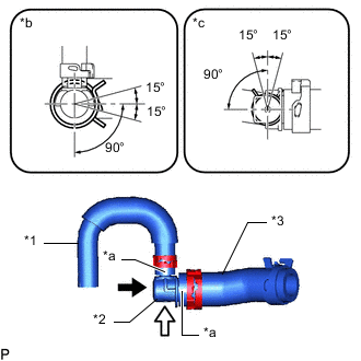
*1 No. 4 Fuel Vapor Feed Hose *2 No. 1 Fuel Vapor Feed Connector *3 No. 6 Fuel Vapor Feed Hose *a Paint Mark *b View A *c View B 
View A 
View B Fuel Vapor Feed Hose Assembly Side:
-
Connect the No. 4 fuel vapor feed hose to the No. 1 fuel vapor feed connector, and slide the clip to secure the hose.
Tech Tips
-
Align the paint mark on the No. 4 fuel vapor feed hose with the positioning stopper on the No. 1 fuel vapor feed connector.
-
Make sure the direction of the clip is as shown in the illustration.
-
-
Connect the No. 6 fuel vapor feed hose to the No. 1 fuel vapor feed connector, and slide the clip to secure the hose.
Tech Tips
-
Align the paint mark on the No. 6 fuel vapor feed hose with the positioning stopper on the No. 1 fuel vapor feed connector.
-
Make sure the direction of the clip is as shown in the illustration.
-
-
-
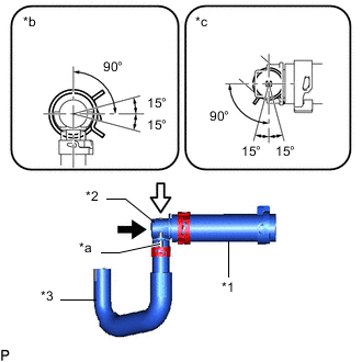
*1 No. 5 Fuel Vapor Feed Hose *2 No. 1 Fuel Vapor Feed Connector *3 No. 7 Fuel Vapor Feed Hose *a Paint Mark *b View A *c View B View A View B No. 2 Fuel Vapor Feed Hose Assembly Side:
-
Connect the No. 5 fuel vapor feed hose to the No. 1 fuel vapor feed connector, and slide the clip to secure the hose.
Tech Tips
-
Align the paint mark on the No. 5 fuel vapor feed hose with the positioning stopper on the No. 1 fuel vapor feed connector.
-
Make sure the direction of the clip is as shown in the illustration.
-
-
Connect the No. 7 fuel vapor feed hose to the No. 1 fuel vapor feed connector, and slide the clip to secure the hose.
Tech Tips
-
Connect the No. 5 fuel vapor feed hose to the No. 1 fuel vapor feed connector at the position shown in the illustration.
-
Make sure the direction of the clip is as shown in the illustration.
-
-
-
-
INSTALL NO. 1 CHECK VALVE
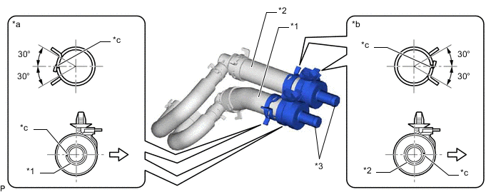
*1 No. 4 Fuel Vapor Feed Hose *2 No. 5 Fuel Vapor Feed Hose *3 No. 1 Check Valve - - *a Fuel Vapor Feed Hose Assembly Side *b No. 2 Fuel Vapor Feed Hose Assembly Side *c Paint Mark - - Engine Front - -
-
Fuel Vapor Feed Hose Assembly Side:
-
Connect the No. 1 check valve to the No. 5 fuel vapor feed hose, and slide the clip to secure the hose.
Tech Tips
Align the direction of the claw on the clip with the paint mark on the hose.
-
-
No. 2 Fuel Vapor Feed Hose Assembly Side:
-
Connect the No. 1 check valve to the No. 4 fuel vapor feed hose, and slide the clip to secure the hose.
Tech Tips
Align the direction of the claw on the clip with the paint mark on the hose.
-
-
-
INSTALL NO. 2 FUEL VAPOR FEED HOSE
-
Install the 2 No. 2 fuel vapor feed hoses to the 2 No. 1 check valves.
-
-
INSTALL NO. 2 FUEL VAPOR FEED PIPE
-
Install the No. 2 fuel vapor feed pipe to the 2 fuel vapor feed hoses.
-
-
INSTALL VACUUM SWITCHING VALVE BRACKET SUB-ASSEMBLY
-
Attach the 2 clamps and install the 2 No. 1 check valves to the vacuum switching valve bracket sub-assembly.
-
-
INSTALL PURGE VSV
-
Install the purge VSV to the vacuum switching valve bracket sub-assembly with the screw.
- Torque:
- 3.4 N*m { 35 kgf*cm, 30 in.*lbf }
-
Install the No. 1 fuel vapor feed hose.
-
-
INSTALL NO. 1 VACUUM SWITCHING VALVE ASSEMBLY
-
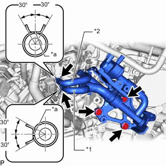
*1 No. 6 Fuel Vapor Feed Hose *2 No. 7 Fuel Vapor Feed Hose *a Paint Mark Install the No. 1 vacuum switching valve assembly to the cylinder head sub-assembly RH with the 3 bolts.
- Torque:
- 21 N*m { 214 kgf*cm, 15 ft.*lbf }
-
Connect the No. 6 fuel vapor feed hose to the fuel vapor feed pipe sub-assembly, and slide the clip to secure the hose.
Tech Tips
Make sure the direction of the clip is as shown in the illustration.
-
Connect the No. 7 fuel vapor feed hose to the fuel vapor feed pipe sub-assembly, and slide the clip to secure the hose.
Tech Tips
Make sure the direction of the clip is as shown in the illustration.
-
Connect the purge VSV connector.
-
-
INSTALL NO. 2 TURBO INSULATOR
-
INSTALL FUEL PIPE PROTECTOR BRACKET
-
Install the fuel pipe protector bracket with the 4 bolts.
- Torque:
- 21 N*m { 214 kgf*cm, 15 ft.*lbf }
-
-
INSTALL WIRE HARNESS CLAMP BRACKET (for LHD)
-
Install the wire harness clamp bracket with the 2 bolts.
- Torque:
- 10 N*m { 102 kgf*cm, 7 ft.*lbf }
-
Attach the 2 clamps and connect the No. 2 engine wire.
-
-
CONNECT ENGINE WIRE
-
for LHD:
-
Attach the 3 clamps and connect the engine wire with the bolt.
- Torque:
- 10 N*m { 102 kgf*cm, 7 ft.*lbf }
-
Connect the 4 connectors.
-
-
for RHD:
-
Attach the 4 clamps and connect the engine wire with the bolt.
- Torque:
- 10 N*m { 102 kgf*cm, 7 ft.*lbf }
-
Connect the 4 connectors.
-
-
-
INSTALL FUEL VAPOR FEED PIPE
-
Install the fuel vapor feed hose to the No. 1 vacuum switching valve assembly.
-
Install the fuel vapor feed pipe to the No. 1 engine cover bracket with the 2 bolts.
- Torque:
- 10 N*m { 102 kgf*cm, 7 ft.*lbf }
-
-
CONNECT NO. 1 FUEL VAPOR FEED HOSE
-
Connect the No. 1 fuel vapor feed hose to the fuel vapor feed pipe, and slide the clip to secure the hose.
-
-
INSTALL V-BANK COVER SUB-ASSEMBLY
-
INSTALL NO. 2 TURBO PRESSURE SENSOR (for Bank 2)
-
INSTALL NO. 2 TURBO PRESSURE SENSOR (for Bank 1)
-
INSTALL AIR FUEL RATIO SENSOR (for Bank 1 Sensor 1)
-
INSTALL COWL TOP VENTILATOR LOUVER SUB-ASSEMBLY