METER / GAUGE SYSTEM, Diagnostic DTC:B1500
| DTC Code | DTC Name |
|---|---|
| B1500 | Fuel Sender Open Detected |
DESCRIPTION
This DTC is stored when the combination meter detects the fuel sender gauge malfunction.
| DTC No. | DTC Detection Condition | Trouble Area |
|---|---|---|
| B1500 | When combination meter detects fuel sender gauge malfunction |
|
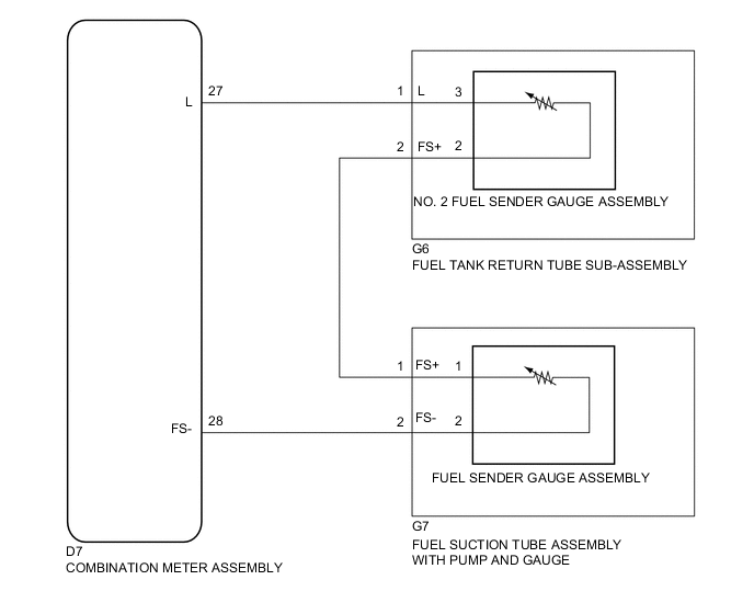
WIRING DIAGRAM
PROCEDURE
-
READ VALUE USING GTS (FUEL INPUT)
-
Connect the GTS to the DLC3.
-
Turn the ignition switch to ON.
-
Turn the GTS on.
-
Enter the following menus: Body Electrical / Combination Meter / Data List.
-
According to the display on the tester, read the Data List.
Combination Meter Item Measurement Item/Range Normal Condition Diagnostic Note Fuel Input Fuel sender gauge input
Min.: 0
Max.: 127.5
Fuel sender input value Unit: Liter OK Fuel input signal displayed on the tester is approximately the same as the fuel receiver gauge indication.
OK 
REPLACE COMBINATION METER ASSEMBLY Click here
NG 
-
-
INSPECT FUEL SENDER GAUGE ASSEMBLY
-
Remove the fuel sender gauge assembly Click here.
-
Inspect the fuel sender gauge assembly Click here.
NG
REPLACE FUEL SENDER GAUGE ASSEMBLY Click here
OK
-
-
INSPECT FUEL SUCTION TUBE ASSEMBLY WITH PUMP AND GAUGE
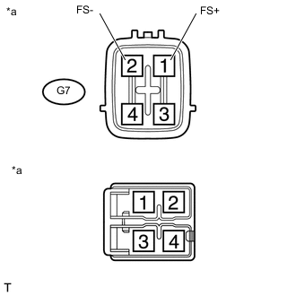
Text in Illustration *a Component without harness connected
(Fuel Suction Tube Assembly with Pump and Gauge)
-
Remove the fuel suction tube assembly with pump and gauge Click here.
-
Measure the resistance according to the value(s) in the table below.
Standard Resistance Tester Connector Condition Specified Condition G7-1 (FS+) - 1 Always Below 1 Ω G7-2 (FS-) - 2 Always Below 1 Ω
NG
REPLACE FUEL SUCTION TUBE ASSEMBLY WITH PUMP AND GAUGE Click here
OK
-
-
INSPECT NO. 2 FUEL SENDER GAUGE ASSEMBLY
-
Remove the No. 2 fuel sender gauge assembly Click here.
-
Inspect the No. 2 fuel sender gauge assembly Click here.
NG
REPLACE NO. 2 FUEL SENDER GAUGE ASSEMBLY Click here
OK
-
-
INSPECT FUEL TANK RETURN TUBE SUB-ASSEMBLY
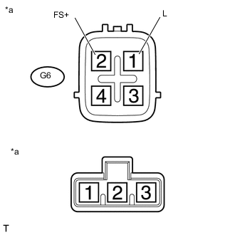
Text in Illustration *a Component without harness connected
(Fuel Tank Return Tube Sub-assembly)
-
Remove the fuel tank return tube sub-assembly Click here.
-
Measure the resistance according to the value(s) in the table below.
Standard Resistance Tester Connector Condition Specified Condition G6-1 (L) - 3 Always Below 1 Ω G6-2 (FS+) - 2 Always Below 1 Ω
NG
REPLACE FUEL TANK RETURN TUBE SUB-ASSEMBLY Click here
OK
-
-
CHECK HARNESS AND CONNECTOR (COMBINATION METER ASSEMBLY - FUEL SUCTION TUBE ASSEMBLY WITH PUMP AND GAUGE)
-
Disconnect the D7 combination meter assembly connector.
-
Disconnect the G7 fuel suction tube assembly with pump and gauge connector.
-
Measure the resistance according to the value(s) in the table below.
Standard Resistance (Check for Open) Tester Connector Condition Specified Condition D7-28 (FS-) - G7-2 (FS-) Always Below 1 Ω Standard Resistance (Check for Short) Tester Connector Condition Specified Condition D7-28 (FS-) or G7-2 (FS-) - Body ground Always 10 kΩ or higher
NG
REPAIR OR REPLACE HARNESS OR CONNECTOR
OK
-
-
CHECK HARNESS AND CONNECTOR (FUEL SUCTION TUBE ASSEMBLY WITH PUMP AND GAUGE - FUEL TANK RETURN TUBE SUB-ASSEMBLY)
-
Disconnect the G7 fuel suction tube assembly with pump and gauge connector.
-
Disconnect the G6 fuel tank return tube sub-assembly connector.
-
Measure the resistance according to the value(s) in the table below.
Standard Resistance (Check for Open) Tester Connector Condition Specified Condition D7-1 (FS+) - G6-2 (FS+) Always Below 1 Ω Standard Resistance (Check for Short) Tester Connector Condition Specified Condition D7-1 (FS+) or G6-2 (FS+) - Body ground Always 10 kΩ or higher
NG
REPAIR OR REPLACE HARNESS OR CONNECTOR
OK
-
-
CHECK HARNESS AND CONNECTOR (COMBINATION METER ASSEMBLY - FUEL TANK RETURN TUBE SUB-ASSEMBLY)
-
Disconnect the D7 combination meter assembly connector.
-
Disconnect the G6 fuel tank return tube sub-assembly connector.
-
Measure the resistance according to the value(s) in the table below.
Standard Resistance (Check for Open) Tester Connector Condition Specified Condition D7-27 (L) - G6-1 (L) Always Below 1 Ω Standard Resistance (Check for Short) Tester Connector Condition Specified Condition D7-27 (L) or G6-1 (L) - Body ground Always 10 kΩ or higher
OK
REPLACE COMBINATION METER ASSEMBLY Click here
NG
REPAIR OR REPLACE HARNESS OR CONNECTOR
-