COMPRESSOR(for V35A-FTS AWD) INSTALLATION

CAUTION / NOTICE / HINT
Note
Check that coolant (including intercooler coolant) is being sufficiently supplied when starting the engine
Note
for HFO-1234yf (R1234yf):
-
Always use ND-OIL 12 as the compressor oil.
-
The oil used for HFC-134a (R134a) systems (ND-OIL 8) does not work well in HFO-1234yf (R1234yf) systems. If the oil used for HFC-134a (R134a) systems (ND-OIL 8) is used in an HFO-1234yf (R1234yf) system, it will result in degradation of the refrigerant and deterioration of resin parts.
for HFC-134a (R134a):
-
The recommended compressor oil listed on the compressor assembly and on the engine hood may differ. Make sure to use the compressor oil listed on the engine hood.
-
If ND-OIL 12 is mixed with the ND-OIL 8 in the system, the performance of the air conditioning system will not be affected.
PROCEDURE
-
ADJUST COMPRESSOR OIL
-
When replacing the compressor assembly with pulley with a new one, gradually discharge the inert gas (helium) from the service valve, and drain the following amount of oil before installation.
Note
-
If a new compressor assembly with pulley is installed without removing the same amount of compressor oil as is remaining in the pipes, the amount of compressor oil will be excessive. This prevents heat exchange in the refrigerant cycle and will cause the air conditioning system to malfunction.
-
A certain amount of compressor oil remains in the compressor assembly with pulley during circulation and the compressor may be damaged if the amount of compressor oil is more/less than this amount. Therefore, make sure to adjust the amount of compressor oil correctly.
-
If the amount of compressor oil remaining in the removed compressor assembly with pulley is excessively low, check for compressor oil leaks.
-
for HFC-134a(R134a): Make sure to use ND-OIL 8 or equivalent compressor oil.
-
for HFO-1234yf(R1234yf): Make sure to use ND-OIL 12 or equivalent compressor oil.
-
-
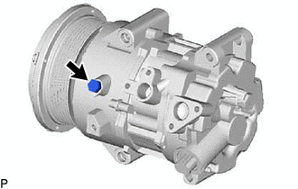
Remove the drain bolt (seal washer) from the removed compressor assembly with pulley.
-
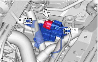
Drain the compressor oil from the oil port of the removed compressor assembly with pulley as shown in the illustration.
Note
Make sure to drain the compressor oil from the oil port.
*a Oil Port *b Turn Clockwise -
Remove the drain bolt (seal washer) from the new compressor assembly with pulley.
Tech Tips
The drain bolt (seal washer) can be reused.
-
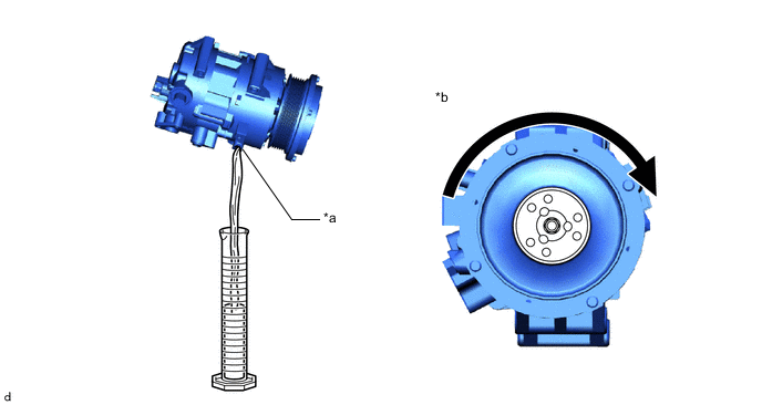
Drain the following amount of compressor oil from the oil port of the new compressor assembly with pulley as shown in the illustration.
Standard (The amount of oil in a new compressor assembly with pulley: 100 to 115 cc (3.38 to 3.89 fl.oz)) - (The amount of oil in the removed compressor assembly with pulley) = The amount of oil to be removed from the new compressor assembly with pulley. Note
-
Make sure to drain the compressor oil from the oil port.
-
Make sure to add the compressor oil from the oil port, not from the discharge or intake port.
-
If a tool is used to add compressor oil to the new compressor assembly with pulley, make sure that it is free of foreign matter.
-
If the amount of compressor oil remaining in the removed compressor assembly with pulley cannot be estimated because the compressor was damaged and oil was discharged due to a frontal collision, etc., install the new compressor assembly with pulley without removing any oil. If the cooler condenser assembly is also replaced, do not add the specified amount of compressor oil for cooler condenser assembly replacement (40 cc (1.35 fl.oz)).
*a Oil Port *b Turn Clockwise -
-
Install the drain bolt (seal washer) to the new compressor assembly with pulley.
- Torque:
- 30 N*m { 306 kgf*cm, 22 ft.*lbf }
Note
Make sure that there is no damage or foreign matter on the seal washer edge.
-
-
INSTALL COMPRESSOR ASSEMBLY WITH PULLEY
-
Using an E8 "TORX" socket wrench, install the 2 stud bolts.
- Torque:
- 10 N*m { 102 kgf*cm, 7 ft.*lbf }
-
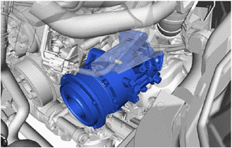
temporarily install the compressor assembly with pulley.
-
temporarily install the oil filter bracket.
-
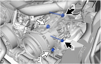

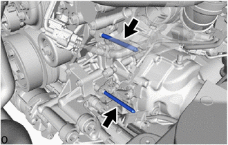
Bolt 
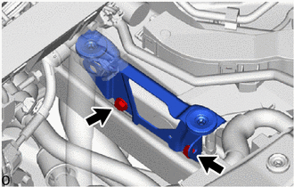
Nut Install the compressor assembly with pulley with the 2 nuts and 2 bolts.
Note
Tighten the 2 nuts and 2 bolts in the order shown in the illustration.
- Torque:
- Nut, Bolt
- 24.5 N*m { 250 kgf*cm, 18 ft.*lbf }
-
Connect the connector.
-
-
INSTALL SUCTION HOSE SUB-ASSEMBLY
-
Remove the vinyl tape from the suction hose sub-assembly and connecting part of the compressor assembly with pulley.
-
Sufficiently apply compressor oil to a new O-ring and the fitting surface of the compressor assembly with pulley.
Compressor Oil Refrigerant Compressor Oil HFC-134a (R134a) ND-OIL 8 or equivalent HFO-1234yf (R1234yf) ND-OIL 12 or equivalent -
Install the O-ring to the suction hose sub-assembly.
Note
Keep the O-ring and O-ring fitting surface free of foreign matter.
-
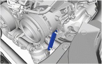
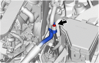
Install the suction hose sub-assembly to the compressor assembly with pulley with the bolt.
- Torque:
- 9.8 N*m { 100 kgf*cm, 87 in.*lbf }
Note
-
Do not apply excessive force to the suction hose sub-assembly.
-
Make sure not to cut the O-ring while installing it. (Cut O-rings cannot be installed)
-
-
CONNECT DISCHARGE HOSE SUB-ASSEMBLY
-
Remove the vinyl tape from the discharge hose sub-assembly and connecting part of the compressor assembly with pulley.
-
Sufficiently apply compressor oil to a new O-ring and the fitting surface of the compressor assembly with pulley.
Compressor Oil Refrigerant Compressor Oil HFC-134a (R134a) ND-OIL 8 or equivalent HFO-1234yf (R1234yf) ND-OIL 12 or equivalent -
Install the O-ring to the discharge hose sub-assembly.
Note
Keep the O-ring and O-ring fitting surface free of foreign matter.
-
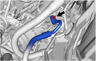
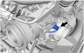
Connect the discharge hose sub-assembly to the compressor assembly with pulley with the bolt.
- Torque:
- 9.8 N*m { 100 kgf*cm, 87 in.*lbf }
Note
-
Do not apply excessive force to the discharge hose sub-assembly.
-
Make sure not to cut the O-ring while installing it. (Cut O-rings cannot be installed)
-
-
INSTALL THROTTLE BODY WITH MOTOR ASSEMBLY (for Bank 2)
-
INSTALL NO. 2 AIR TUBE ASSEMBLY
-
INSTALL AIR CLEANER SUPPORT BRACKET ASSEMBLY
-
Install the air cleaner support bracket assembly with the 2 bolts.
- Torque:
- 10 N*m { 102 kgf*cm, 7 ft.*lbf }
-
-
INSTALL NO. 13 CONNECTOR HOLDER
-
*a Clamp *b Guide Attach the clamp to install the No. 13 connector holder to the air cleaner support bracket assembly.
-
Connect the connector.
-
-
CONNECT SUCTION HOSE SUB-ASSEMBLY
-
Remove the vinyl tape from the suction hose sub-assembly and air conditioning tube and accessory assembly.
-
Sufficiently apply compressor oil to a new O-ring and the fitting surface of the air conditioning tube and accessory assembly.
Compressor Oil Refrigerant Compressor Oil HFC-134a (R134a) ND-OIL 8 or equivalent HFO-1234yf (R1234yf) ND-OIL 12 or equivalent -
Install the O-ring to the suction hose sub-assembly.
Note
Keep the O-ring and O-ring fitting surface free of foreign matter.
-
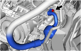
Connect the suction hose sub-assembly to the air conditioning tube and accessory assembly with the nut.
- Torque:
- 9.8 N*m { 100 kgf*cm, 87 in.*lbf }
Note
-
Do not apply excessive force to the suction hose sub-assembly and air conditioning tube and accessory assembly.
-
Make sure not to cut the O-ring while installing it. (Cut O-rings cannot be installed)
-
-
INSTALL WATER PUMP BRACKET SUB-ASSEMBLY
-
CONNECT INTERCOOLER COOLING WATER INLET HOSE
-
INSTALL INTERCOOLER RESERVE TANK ASSEMBLY
-
INSTALL AIR CLEANER WITH ELEMENT ASSEMBLY RH
-
INSTALL AIR CLEANER WITH ELEMENT ASSEMBLY LH
-
INSTALL RADIATOR SUPPORT TO CROSSMEMBER BRACE SUB-ASSEMBLY RH
-
Install the radiator support to crossmember brace sub-assembly RH with the 2 bolts.
- Torque:
- 49 N*m { 500 kgf*cm, 36 ft.*lbf }
-
-
INSTALL RADIATOR SUPPORT TO CROSSMEMBER BRACE SUB-ASSEMBLY LH
-
Install the radiator support to crossmember brace sub-assembly LH with the 2 bolts.
- Torque:
- 49 N*m { 500 kgf*cm, 36 ft.*lbf }
-
-
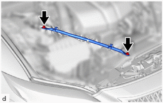
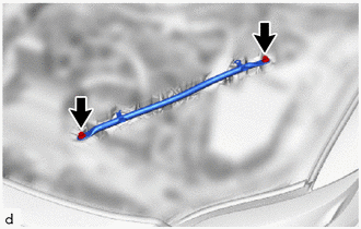
INSTALL NUT
-
Using a 12 mm union nut wrench and SST, install the nut.
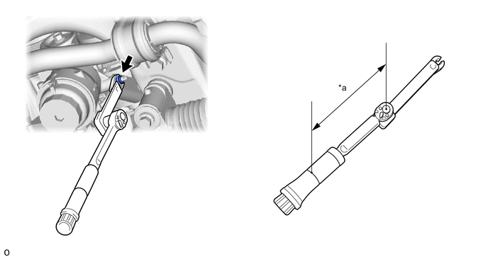
*a Torque Wrench Fulcrum Length - - - SST
- 09961-00950
- Torque:
- Specified tightening torque
- 24.5 N*m { 250 kgf*cm, 18 ft.*lbf }
Tech Tips
-
Calculate the torque wrench reading when changing the fulcrum length of the torque wrench.
-
When using a union nut wrench (fulcrum length of 20 mm (0.787 in.)) + SST (fulcrum length of 150 mm (5.906 in.)) + torque wrench (fulcrum length of 162 mm (6.378 in.)): 12 N*m (122 kgf*cm, 9 ft.*lbf)
-
-
INSTALL FAN AND GENERATOR V BELT
-
CHARGE AIR CONDITIONING SYSTEM WITH REFRIGERANT
-
for HFC-134a(R134a):
-
for HFO-1234yf(R1234yf):
-
-
ADD ENGINE COOLANT
-
ADD COOLANT (for Intercooler)
-
INSPECT FOR COOLANT LEAK
-
INSPECT FOR COOLANT LEAK (for Intercooler)
-
WARM UP ENGINE
-
for HFC-134a(R134a):
-
for HFO-1234yf(R1234yf):
-
-
INSPECT FOR REFRIGERANT LEAK
-
for HFC-134a(R134a):
-
for HFO-1234yf(R1234yf):
-
-
INSTALL ENGINE UNDER COVER BRACKET RH
-
INSTALL STRUT BAR BRACKET SUPPORT SUB-ASSEMBLY
-
INSTALL FRONT SUSPENSION MEMBER BRACE
-
INSTALL NO. 1 ENGINE UNDER COVER ASSEMBLY
-
INSTALL LOWER RADIATOR AIR DEFLECTOR
-
INSTALL UPPER RADIATOR SUPPORT SEAL
-
INSTALL RADIATOR COVER PLATE
-
INSTALL V-BANK COVER SUB-ASSEMBLY