ROOF ANTENNA REMOVAL
CAUTION / NOTICE / HINT
The necessary procedures (adjustment, calibration, initialization, or registration) that must be performed after parts are removed and installed, or replaced during telephone antenna assembly removal/installation are shown below.
| Replaced Part or Performed Procedure | Necessary Procedure | Effect/Inoperative Function when Necessary Procedure not Performed | Link |
|---|---|---|---|
| Disconnect cable from negative battery terminal | Memorize steering angle neutral point | LKA/LDA System | |
| Intelligent clearance sonar system*1 | |||
| Pre-crash safety system | |||
| Lighting system (EXT)
|
|||
| Adaptive high beam system | |||
| Drive the vehicle until stop and start control is permitted (approximately 15 to 60 minutes) | Stop and start system | ||
| Memorize steering angle neutral point | Parking assist monitor system (w/ Parallel parking assist function) | ||
| Parking assist monitor system (w/o Parallel parking assist function) | |||
| Panoramic view monitor system | |||
| Initialize back door lock | Power door lock control system | ||
| Reset back door close position | Power back door system |
*1: When performing learning using the GTS.
CAUTION:
Some of these service operations affect the SRS airbag system. Read the precautionary notices concerning the SRS airbag system before servicing.
PROCEDURE
-
REMOVE ROOF HEADLINING ASSEMBLY
-
REMOVE TELEPHONE ANTENNA ASSEMBLY WITH COVER
-
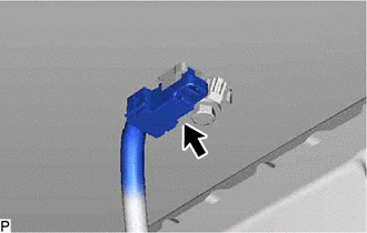
Disconnect the connector.
-
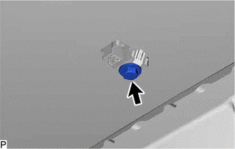
Remove the bolt.
-
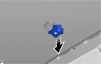

Remove in this Direction Pull the washer and holder as shown in the illustration and remove the telephone antenna assembly with cover.
-
-
REMOVE TELEPHONE ANTENNA ASSEMBLY
-
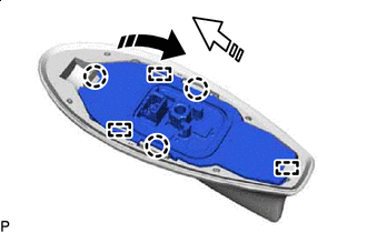
Remove in this Direction (1) 
Remove in this Direction (2) Pull the telephone antenna assembly in the direction indicated by the arrow (1) shown in the illustration to disengage the 3 claws and 2 guides.
-
Pull the telephone antenna assembly in the direction indicated by the arrow (2) shown in the illustration to disengage the guide and remove the telephone antenna assembly.
-
When reusing the telephone antenna assembly:
-
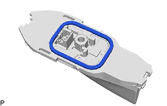
Remove the seal.
-
-