OIL PUMP REMOVAL

CAUTION / NOTICE / HINT
The necessary procedures (adjustment, calibration, initialization, or registration) that must be performed after parts are removed, installed, or replaced during the timing chain cover assembly removal/installation are shown below.
| Replacement Part or Procedure | Necessary Procedure | Effect/Inoperative when not Performed | Link |
|---|---|---|---|
| Disconnect cable from negative battery terminal | Drive the vehicle until stop and start control is permitted (approximately 5 to 60 minutes) | Stop and start system | |
| Memorize steering angle neutral point | LKA/LDA system | ||
| Parking support brake system*1 | |||
| Pre-collision system | |||
| Adaptive high beam system | |||
Lighting system (EXT) |
|||
| Variable gear ratio steering system | |||
| Parking assist monitor system | |||
| Panoramic view monitor system | |||
| Initialize rear door sunshade system | Rear door sunshade system | ||
| Initialize power trunk lid system | Power trunk lid system | ||
|
Inspection after repair |
|
|
| Engine assembly | Inspection after repair | ||
|
|
||
| Starter assembly Note When the starter assembly is replaced, "ST NO. 1 relay" and "ST NO. 2 relay" must be also replaced. |
Clear number of starter operations | Stop and start system | |
| Automatic transmission assembly |
|
|
for Initialization: for Registration: |
| Automatic transmission fluid | ATF thermal degradation estimate reset | The value of the Data List item "ATF Thermal Degradation Estimate" is not estimated correctly. | |
| Wheel alignment adjustment |
|
|
|
| Front bumper assembly (Including removal and installation) |
|
Parking support brake system | |
| Front television camera view adjustment | Panoramic view monitor system | ||
| Suspension, tires, etc. |
|
Parking support brake system | |
|
Panoramic view monitor system | ||
| Rear television camera assembly optical axis (Back camera position setting) | Parking assist monitor system | ||
| Parts between the steering wheel and tires have been removed/installed, replaced or adjusted | Perform actuator angle neutral point calibration and initialization |
|
Click here Click here
*2: Set the transmission compensation code for the new automatic transmission.
PROCEDURE
-
REMOVE ENGINE AND TRANSMISSION
-
REMOVE ENGINE WIRE
-
REMOVE INTAKE AIR SURGE TANK ASSEMBLY
-
REMOVE FAN AND GENERATOR V BELT
-
REMOVE GENERATOR ASSEMBLY
-
REMOVE V-RIBBED BELT TENSIONER ASSEMBLY
-
REMOVE NO. 1 IDLER PULLEY SUB-ASSEMBLY
-
REMOVE COMPRESSOR ASSEMBLY WITH PULLEY
-
REMOVE NO. 1 COMPRESSOR MOUNTING BRACKET
-
REMOVE WATER BY-PASS PIPE ASSEMBLY
-
REMOVE WATER HOSE SUB-ASSEMBLY
-
REMOVE NO. 6 WATER BY-PASS HOSE
-
REMOVE NO. 2 WATER BY-PASS HOSE
-
REMOVE WATER OUTLET
-
REMOVE WATER PUMP PULLEY
-
REMOVE CAMSHAFT TIMING OIL CONTROL SOLENOID ASSEMBLY (for Intake Side of Bank 1)
-
REMOVE CAMSHAFT TIMING OIL CONTROL SOLENOID ASSEMBLY (for Exhaust Side of Bank 1)
-
REMOVE CAMSHAFT TIMING OIL CONTROL SOLENOID ASSEMBLY (for Intake Side of Bank 2)
-
REMOVE CAMSHAFT TIMING OIL CONTROL SOLENOID ASSEMBLY (for Exhaust Side of Bank 2)
-
REMOVE OIL FILTER BRACKET SUB-ASSEMBLY
-
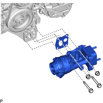
Remove the 2 bolts, 2 nuts, oil filter bracket sub-assembly and gasket.
-
-
REMOVE CRANKSHAFT PULLEY
-
REMOVE NO. 1 ENGINE COVER SUB-ASSEMBLY
-
for Bank 1:
Remove the 2 clips and No. 1 engine cover sub-assembly from the cylinder head cover sub-assembly.
-
for Bank 2:
Remove the clip and No. 1 engine cover sub-assembly from the No. 1 fuel pipe sub-assembly.
-
-
REMOVE NO. 1 FUEL TUBE SUB-ASSEMBLY
-
REMOVE FUEL PUMP ASSEMBLY (for High Pressure)
-
REMOVE IGNITION COIL ASSEMBLY
-
REMOVE CYLINDER HEAD COVER SUB-ASSEMBLY LH
-
Remove the 2 bolts and 2 VVT sensors from the cylinder head cover sub-assembly LH.
-
Remove the 14 bolts and cylinder head cover sub-assembly LH from the camshaft housing sub-assembly.
-
Remove the camshaft bearing cap oil hole gasket.
-
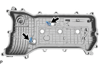
Remove the 2 gaskets and cylinder head cover gasket.
-
-
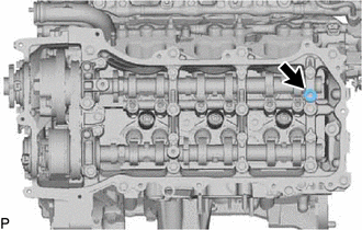
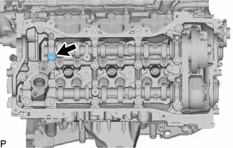
REMOVE CYLINDER HEAD COVER SUB-ASSEMBLY
-
Remove the 2 bolts and 2 VVT sensors from the cylinder head cover sub-assembly.
-
Remove the 13 bolts and cylinder head cover sub-assembly from the camshaft housing sub-assembly.
-
Remove the camshaft bearing cap oil hole gasket.
-
Remove the 2 gaskets and cylinder head cover gasket.
-
-
REMOVE SPARK PLUG TUBE GASKET
-
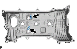
REMOVE NO. 2 OIL PAN SUB-ASSEMBLY
-

Bolt 
Nut Remove the 15 bolts and 2 nuts.
-
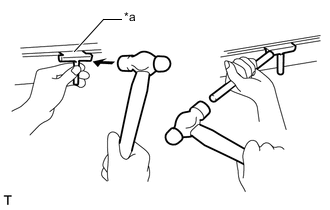
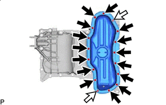
*a Oil Pan Seal Cutter Insert the blade of an oil pan seal cutter between the oil pans. Cut through the applied sealer and remove the No. 2 oil pan sub-assembly.
Note
Be careful not to damage the contact surfaces of the oil pans.
-
-
REMOVE ENGINE OIL LEVEL SENSOR
-
REMOVE OIL LEVEL SENSOR BRACKET
-
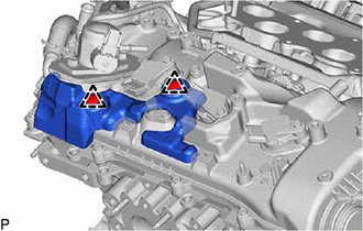
REMOVE OIL PAN SUB-ASSEMBLY
-
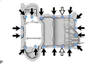
Bolt Nut Remove the 16 bolts and 2 nuts.
Tech Tips
Be sure to clean the bolts and stud bolts and check the threads for cracks or other damage.
-
Remove the oil pan sub-assembly by prying between the oil pan sub-assembly and cylinder block sub-assembly with a screwdriver.
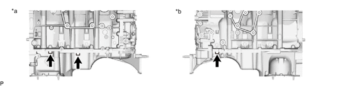
*a RH Side *b LH Side Note
Be careful not to damage the contact surfaces of the cylinder block sub-assembly and oil pan sub-assembly.
Tech Tips
Tape the screwdriver tip before use.
-
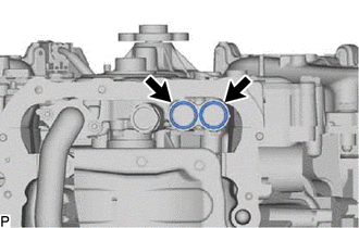
Remove the 2 O-rings from the timing chain cover assembly.
-
-
REMOVE OIL STRAINER SUB-ASSEMBLY
-
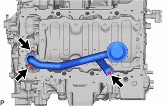
Remove the 3 nuts, oil strainer sub-assembly and gasket.
-
-
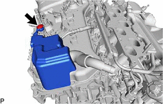
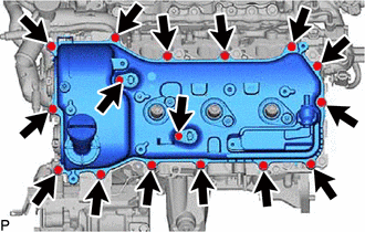
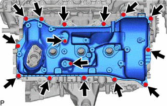
REMOVE TIMING CHAIN COVER ASSEMBLY
-
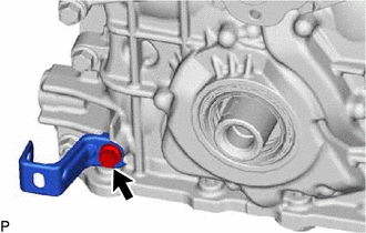
Remove the bolt and wire harness clamp bracket.
-
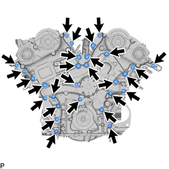
Remove the 26 bolts and 2 nuts shown in the illustration.
-
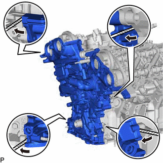
Remove the timing chain cover by prying between the timing chain cover and cylinder head or cylinder block with a screwdriver.
Note
Be careful not to damage the contact surfaces of the cylinder head sub-assembly, cylinder block sub-assembly and chain cover assembly.
Tech Tips
Tape the screwdriver tip before use.
-
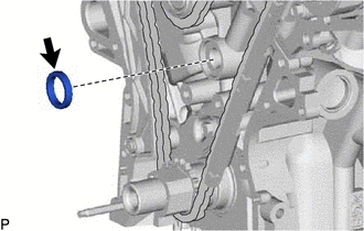
Remove the oil pump gasket from the cylinder block sub-assembly.
-
-
REMOVE TIMING CHAIN CASE OIL SEAL
-
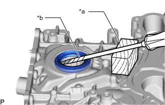
*a Wooden Block *b Protective Tape Using a screwdriver and wooden block, pry out the oil seal.
Note
Do not damage the surface of the oil seal press fit hole.
Tech Tips
Tape the screwdriver tip before use.
-