METER / GAUGE SYSTEM Fuel Gauge Malfunction
DESCRIPTION
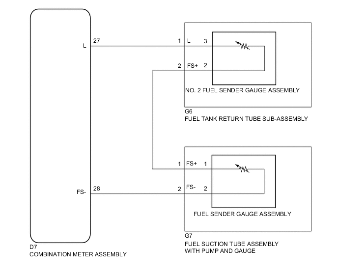
The combination meter assembly controls the fuel receiver gauge in accordance with the resistance of the fuel sender gauge, which varies depending on the amount of fuel remaining in the fuel tank.
WIRING DIAGRAM
PROCEDURE
-
CONFIRM DTC OUTPUT
-
Check DTC Click here.
Result Result Proceed to DTC B1500 is not output A DTC B1500 is output B
B 
GO TO DIAGNOSTIC TROUBLE CODE CHART Click here
A 
-
-
PERFORM ACTIVE TEST USING GTS (FUEL METER OPERATION)
-
Connect the GTS to the DLC3.
-
Turn the ignition switch to ON.
-
Turn the GTS on.
-
Enter the following menus: Body Electrical / Combination Meter / Active Test.
-
According to the display on the tester, perform the Active Test.
Combination Meter Tester Display Test part Control Range Diagnostic Note Fuel Meter Operation Fuel gauge EMPTY, 1/2, FULL -
NG
REPLACE COMBINATION METER ASSEMBLY Click here
OK
-
-
READ VALUE USING GTS (FUEL INPUT)
-
Connect the GTS to the DLC3.
-
Turn the ignition switch to ON.
-
Turn the GTS on.
-
Enter the following menus: Body Electrical / Combination Meter / Data List.
-
According to the display on the tester, read the Data List.
Combination Meter Item Measurement Item/Range Normal Condition Diagnostic Note Fuel Input Fuel sender gauge input
Min.: 0
Max.: 127.5
Fuel sender input value Unit: Liter OK Fuel input signal displayed on the tester is approximately the same as the fuel receiver gauge indication.
OK
REPLACE COMBINATION METER ASSEMBLY Click here
NG
-
-
INSPECT FUEL SENDER GAUGE ASSEMBLY
-
Remove the fuel sender gauge assembly Click here.
-
Inspect the fuel sender gauge assembly Click here.
B
REPLACE FUEL SENDER GAUGE ASSEMBLY Click here
A
-
-
INSPECT FUEL SUCTION TUBE ASSEMBLY WITH PUMP AND GAUGE
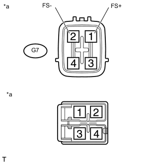
Text in Illustration *a Component without harness connected
(Fuel Suction Tube Assembly with Pump and Gauge)
-
Remove the fuel suction tube assembly with pump and gauge Click here.
-
Measure the resistance according to the value(s) in the table below.
Standard Resistance Tester Connector Condition Specified Condition G7-1 (FS+) - 1 Always Below 1 Ω G7-2 (FS-) - 2 Always Below 1 Ω
B
REPLACE FUEL SUCTION TUBE ASSEMBLY WITH PUMP AND GAUGE Click here
A
-
-
REPLACE NO. 2 FUEL SENDER GAUGE ASSEMBLY
-
Remove the No. 2 fuel sender gauge assembly Click here.
-
Inspect the No. 2 fuel sender gauge assembly Click here.
B
REPLACE NO. 2 FUEL SENDER GAUGE ASSEMBLY Click here
A
-
-
REPLACE FUEL TANK RETURN TUBE SUB-ASSEMBLY
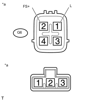
Text in Illustration *a Component without harness connected
(Fuel Tank Return Tube Sub-assembly)
-
Remove the fuel tank return tube sub-assembly Click here.
-
Measure the resistance according to the value(s) in the table below.
Standard Resistance Tester Connector Condition Specified Condition G6-1 (L) - 3 Always Below 1 Ω G6-2 (FS+) - 2 Always Below 1 Ω
B
REPLACE FUEL TANK RETURN TUBE SUB-ASSEMBLY Click here
A
-
-
CHECK HARNESS AND CONNECTOR (COMBINATION METER ASSEMBLY - FUEL SUCTION TUBE ASSEMBLY WITH PUMP AND GAUGE)
-
Disconnect the D7 combination meter assembly connector.
-
Disconnect the G7 fuel suction tube assembly with pump and gauge connector.
-
Measure the resistance according to the value(s) in the table below.
Standard Resistance (Check for Open) Tester Connector Condition Specified Condition D7-28 (FS-) - G7-2 (FS-) Always Below 1 Ω Standard Resistance (Check for Short) Tester Connector Condition Specified Condition D7-28 (FS-) or G7-2 (FS-) - Body ground Always 10 kΩ or higher
NG
REPAIR OR REPLACE HARNESS OR CONNECTOR
OK
-
-
CHECK HARNESS AND CONNECTOR (FUEL SUCTION TUBE ASSEMBLY WITH PUMP AND GAUGE - FUEL TANK RETURN TUBE SUB-ASSEMBLY)
-
Disconnect the G7 fuel suction tube assembly with pump and gauge connector.
-
Disconnect the G6 fuel tank return tube sub-assembly connector.
-
Measure the resistance according to the value(s) in the table below.
Standard Resistance (Check for Open) Tester Connector Condition Specified Condition D7-1 (FS+) - G6-2 (FS+) Always Below 1 Ω Standard Resistance (Check for Short) Tester Connector Condition Specified Condition D7-1 (FS+) or G6-2 (FS+) - Body ground Always 10 kΩ or higher
NG
REPAIR OR REPLACE HARNESS OR CONNECTOR
OK
-
-
CHECK HARNESS AND CONNECTOR (COMBINATION METER ASSEMBLY - FUEL TANK RETURN TUBE SUB-ASSEMBLY)
-
Disconnect the D7 combination meter assembly connector.
-
Disconnect the G6 fuel tank return tube sub-assembly connector.
-
Measure the resistance according to the value(s) in the table below.
Standard Resistance (Check for Open) Tester Connector Condition Specified Condition D7-27 (L) - G6-1 (L) Always Below 1 Ω Standard Resistance (Check for Short) Tester Connector Condition Specified Condition D7-27 (L) or G6-1 (L) - Body ground Always 10 kΩ or higher
OK
REPLACE COMBINATION METER ASSEMBLY Click here
NG
REPAIR OR REPLACE HARNESS OR CONNECTOR
-