LOWER INSTRUMENT PANEL REMOVAL
Tech Tips
-
Use the same procedure for RHD and LHD vehicles.
-
The procedure listed below is for LHD vehicles.
-
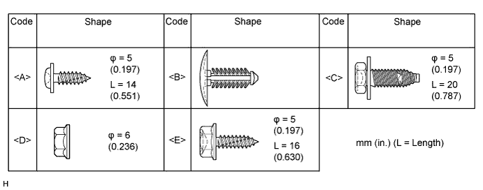
TABLE OF BOLT, SCREW AND NUT
-
All bolts, screws and nuts relevant to installing and removing the instrument panel are shown along with an alphabetical code in the table.
-
-
PRECAUTION (w/ Airbag System)
Note
After turning the ignition switch off, waiting time may be required before disconnecting the cable from the battery terminal. Therefore, make sure to read the disconnecting the cable from the battery terminal notice before proceeding with work Click here.
-
DISCONNECT CABLE FROM NEGATIVE BATTERY TERMINAL (w/ Airbag System)
CAUTION:
Wait at least 90 seconds after disconnecting the cable from the negative (-) battery terminal to disable the SRS system.
Note
When disconnecting the cable, some systems need to be initialized after the cable is reconnected Click here.
-
REMOVE UPPER INSTRUMENT PANEL SUB-ASSEMBLY
-
REMOVE HEADLIGHT DIMMER SWITCH ASSEMBLY
-
REMOVE CONSOLE BOX ASSEMBLY (w/ Console Box)
-
REMOVE FRONT DOOR SCUFF PLATE LH
-
for Double Cab:
-
for Single Cab:
-
for Extra Cab:
-
-
REMOVE FRONT DOOR SCUFF PLATE RH
Tech Tips
Use the same procedure described for the LH side.
-
REMOVE COWL SIDE TRIM BOARD LH
-
Remove the part of the front door opening trim attached to the cowl side trim board.
-
Remove the clip.
-
Detach the 2 clips and remove the cowl side trim.
-
-
REMOVE COWL SIDE TRIM BOARD RH
Tech Tips
Use the same procedure described for the LH side.
-
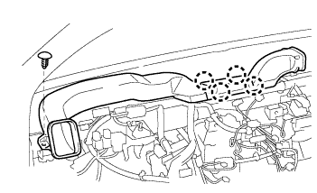
REMOVE NO. 2 HEATER TO REGISTER DUCT
-
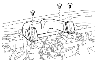
Remove the 3 clips and No. 2 heater to register duct.
-
-
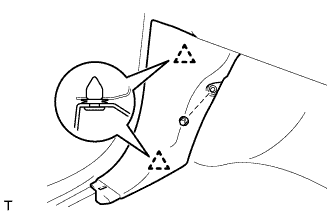
REMOVE NO. 1 HEATER TO REGISTER DUCT
-
Remove the clip.
-
Detach the 3 claws and remove the No. 1 heater to register duct.
-
-
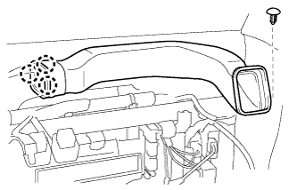
REMOVE NO. 3 HEATER TO REGISTER DUCT
-
Remove the clip.
-
Detach the 4 claws and remove the No. 3 heater to register duct.
-
-
REMOVE LOWER INSTRUMENT PANEL FINISH PANEL SUB-ASSEMBLY
-
Detach the 2 claws, 3 clips and 3 guides and remove the lower instrument panel finish panel.
-
-
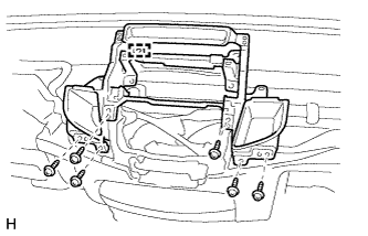
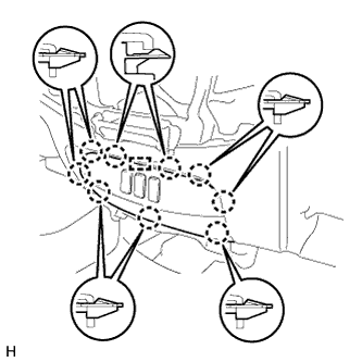
REMOVE NO. 1 INSTRUMENT PANEL BOX
-
Remove the 6 screws <A>.
-
Disconnect the connectors, detach the clamp and remove the No. 1 instrument panel box.
-
-
REMOVE AIR CONDITIONING CONTROL ASSEMBLY (for Manual Air Conditioning System)
-
Disconnect the connector and remove the air conditioning control assembly.
-
-
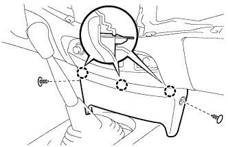
REMOVE LOWER CENTER INSTRUMENT PANEL FINISH PANEL (w/o Console Box)
-
Using a clip remover, remove the 2 clips <B>.
-
Detach the 3 claws and remove the lower center instrument panel finish panel.
-
-
REMOVE GLOVE COMPARTMENT DOOR ASSEMBLY (w/o Front Passenger Airbag)
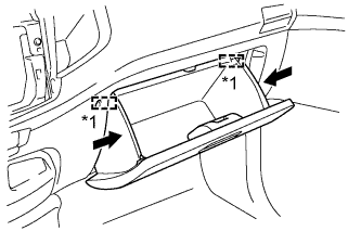
Text in Illustration *1 Stopper
-
Slightly bend the upper part of the glove compartment door to release the 2 stoppers and open the glove compartment door until it is horizontal.
-
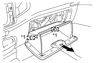
Text in Illustration *1 Hinge Pull the glove compartment door toward the rear of the vehicle to detach the 2 hinges and remove the glove compartment door.
-
-
REMOVE SWITCH BASE
-
Detach the 8 claws.
Tech Tips
If the claws are difficult to detach, detach the claws from the back of the switch base.
-
Disconnect the connectors and remove the switch base..
-
-
REMOVE NO. 1 SWITCH HOLE BASE
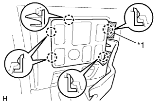
Text in Illustration *1 Protective Tape
-
Put protective tape around the No. 1 switch hole base.
-
Using a moulding remover, detach the 5 claws.
-
Disconnect the connectors and remove the No. 1 switch hole base.
-
-
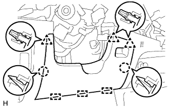
REMOVE LOWER INSTRUMENT PANEL SUB-ASSEMBLY
-
for LHD:
-
Using a clip remover, remove the 2 clips <B>.
-
Remove the 2 bolts <C>, nut <D> and 3 screws <E>.
-
Disconnect the hood lock control cable, fuel lid lock control cable and DLC3.
-
Disconnect the connectors and detach the clamps.
-
Detach the 2 guides and remove the lower instrument panel.
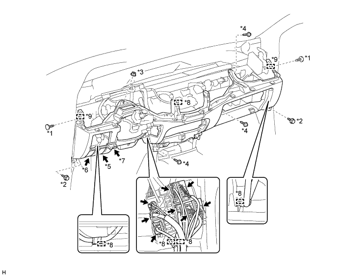
Text in Illustration *1 Clip <B> *2 Bolt <C> *3 Nut <D> *4 Screw <E> *5 Hood Lock Control Cable *6 Fuel Lid Lock Control Cable *7 DLC3 *8 Clamp *9 Guide - -
-
-
for RHD:
-
Using a clip remover, remove the 2 clips <B>.
-
Remove the 2 bolts <C>, nut <D> and 3 screws <E>.
-
Disconnect the hood lock control cable, fuel lid lock control cable and DLC3.
-
Disconnect the connectors and detach the clamps.
-
Detach the 2 guides and remove the lower instrument panel.
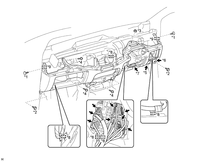
Text in Illustration *1 Clip <B> *2 Bolt <C> *3 Nut <D> *4 Screw <E> *5 Hood Lock Control Cable *6 Fuel Lid Lock Control Cable *7 DLC3 *8 Clamp *9 Guide - -
-
-