AIR CONDITIONING SYSTEM, Diagnostic DTC:B1422/22

| DTC Code | DTC Name |
|---|---|
| B1422/22 | Compressor Lock Sensor Circuit |
DESCRIPTION
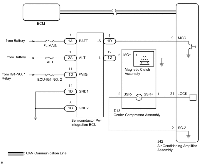
The ECM sends the engine speed signal to the air conditioning amplifier assembly via CAN communication.
The air conditioning amplifier assembly reads the difference between compressor speed and engine speed. When the difference becomes too large, the air conditioning amplifier assembly determines that the compressor is locked, and turns the magnetic clutch assembly off.
| DTC No. | Detection Item | DTC Detection Condition | Trouble Area | Memory |
|---|---|---|---|---|
| B1422/22 | Compressor Lock Sensor Circuit | Open or short in A/C lock sensor circuit |
|
Memorized (3 sec. or more)* |
-
*: The air conditioning amplifier assembly stores this DTC if the malfunction has occurred for the period of time indicated in the brackets.
WIRING DIAGRAM
CAUTION / NOTICE / HINT
Note
ECM malfunctions can affect the storage of this DTC. Therefore, check all SFI system DTCs and confirm that the system is normal before performing the following inspection.
w/ Canister Pump Module: Click here
w/o Canister Pump Module: Click here
PROCEDURE
-
CHECK CAN COMMUNICATION SYSTEM
-
Using the GTS, check if the CAN communication system is functioning normally.
Result Result Proceed to CAN communication system DTCs are not output A CAN communication system DTCs are output B
B 
GO TO CAN COMMUNICATION SYSTEM Click here
A 
-
-
PERFORM ACTIVE TEST USING GTS
-
Disconnect the magnetic clutch assembly connector.
-
Install SST to the connector on the magnetic clutch relay side.
- SST
- 09843-18040
-
Connect the GTS to the DLC3.
-
Start the engine.
-
Turn the GTS on.
-
Enter the following menus: Body Electrical / Air Conditioner / Active Test.
Body Electrical > Air Conditioner > Active TestTester Display Measurement Item Control Range Diagnostic Note Magnetic Clutch Relay Air conditioning system operation OFF, ON - -
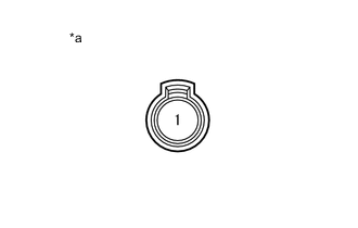
*a Front view of wire harness connector
(to Magnetic Clutch Assembly)
Measure the voltage according to the value(s) in the table below.
Standard Voltage Tester Connection Condition Specified Condition 1 - Body ground
-
Engine is running
-
Active Test above is being performed
11 to 14 V Tech Tips
When performing the Active Test, voltage between 11 and 14 V is output for approximately 3 seconds.
Result Proceed to OK NG -
NG
GO TO AIR CONDITIONING COMPRESSOR MAGNETIC CLUTCH CIRCUIT Click here
OK
-
-
INSPECT MAGNETIC CLUTCH ASSEMBLY
-
Connect the magnetic clutch assembly connector.
-
Disconnect the D13 cooler compressor assembly connector.
-
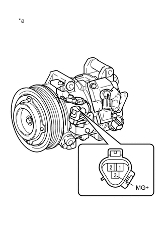
*a Component without harness connected
(Magnetic Clutch Assembly)
Measure the resistance according to the value(s) in the table below.
Standard Resistance Tester Connection Condition Specified Condition 3 (MG+) - Body ground 20°C (68°F) 3.8 to 4.2 Ω -
Connect a positive (+) lead from the battery to terminal 3 (MG+) and check that the following occurs: 1) the magnetic clutch assembly operating sound can be heard, and 2) the magnetic clutch hub and rotor lock.
Result Proceed to OK NG
NG
REPLACE MAGNETIC CLUTCH ASSEMBLY Click here
OK
-
-
INSPECT COOLER COMPRESSOR ASSEMBLY
-
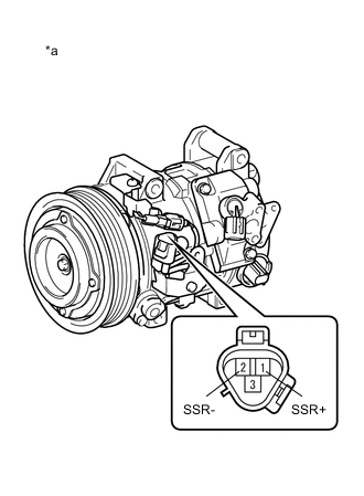
*a Component without harness connected
(Magnetic Clutch Assembly)
Measure the resistance according to the value(s) in the table below.
Standard Resistance Tester Connection Condition Specified Condition 1 (SSR+) - 2 (SSR-) 20°C (68°F) 160 to 320 Ω Result Proceed to OK NG
NG
REPLACE COOLER COMPRESSOR ASSEMBLY Click here
OK
-
-
CHECK HARNESS AND CONNECTOR (COOLER COMPRESSOR ASSEMBLY - AIR CONDITIONING AMPLIFIER ASSEMBLY)
-
Disconnect the J42 air conditioning amplifier assembly connector.
-
Measure the resistance according to the value(s) in the table below.
Standard Resistance Tester Connection Condition Specified Condition D13-1 (SSR+) - J42-21 (LOCK) Always Below 1 Ω D13-2 (SSR-) - J42-2 (SG-2) Always Below 1 Ω J42-21 (LOCK) or D13-1 (SSR+) - Body ground Always 10 kΩ or higher J42-2 (SG-2) or D13-2 (SSR-) - Body ground Always 10 kΩ or higher Result Result Proceed to NG A OK (When troubleshooting according to Problem Symptoms Table) B OK (When troubleshooting according to the DTC) C
A
REPAIR OR REPLACE HARNESS OR CONNECTOR
B
PROCEED TO NEXT SUSPECTED AREA SHOWN IN PROBLEM SYMPTOMS TABLE Click here
C
REPLACE AIR CONDITIONING AMPLIFIER ASSEMBLY Click here
-