REAR LOWER ARM REMOVAL
CAUTION / NOTICE / HINT
The necessary procedures (adjustment, calibration, initialization, or registration) that must be performed after parts are removed and installed, or replaced during rear suspension arm assembly removal/installation are shown below.
| Replaced Part or Performed Procedure | Necessary Procedure | Effect/Inoperative Function when Necessary Procedure not Performed | Link |
|---|---|---|---|
| Rear wheel alignment adjustment |
|
|
|
| Suspension, tires, etc. (The vehicle height changes because of suspension or tire replacement) |
|
|
|
| Rear television camera assembly optical axis (Back camera position setting) | Parking assist monitor system (w/ Parallel Parking Assist Function) | for Initialization: Click here for Calibration: Click here |
|
| Rear television camera assembly optical axis (Back camera position setting) | Parking assist monitor system (w/o Parallel Parking Assist Function) | for Initialization: Click here for Calibration: Click here |
|
|
Panoramic view monitor system | for Initialization: Click here for Calibration: Click here |
|
| Initialize headlight ECU sub-assembly LH |
|
||
| Gas leak from exhaust system is repaired*2 | Inspection After Repair |
|
for 8AR-FTS: Click here for 2GR-FKS w/ Canister Pump Module: Click here for 2GR-FKS w/o Canister Pump Module: Click here |
*2: for RH Side
Tech Tips
-
Use the same procedure for the RH side and LH side.
-
The following procedure is for the LH side.
PROCEDURE
-
REMOVE REAR WHEEL
-
REMOVE TAIL EXHAUST PIPE ASSEMBLY (for RH Side)
for 8AR-FTS: Click here
for 2GR-FKS: Click here
-
REMOVE REAR SUSPENSION ARM COVER
-
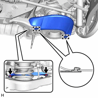
Remove the 2 bolts and rear suspension arm cover from the rear No. 2 suspension arm assembly.
-
-
REMOVE REAR STABILIZER LINK ASSEMBLY
-
REMOVE REAR COIL SPRING
-
REMOVE REAR LOWER COIL SPRING INSULATOR
-
REMOVE REAR NO. 2 SUSPENSION ARM ASSEMBLY
-
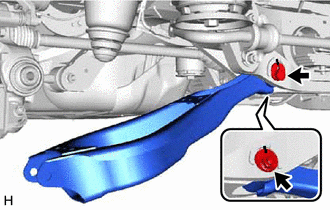
Remove the nut, rear No. 2 suspension camber adjust cam, rear suspension toe adjust cam sub-assembly and rear No. 2 suspension arm assembly.
Note
Hold the rear suspension toe adjust cam sub-assembly while rotating the nut.
-
-
REMOVE REAR NO. 1 SUSPENSION ARM ASSEMBLY (for 2WD)
-
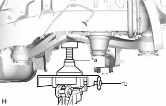
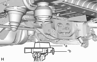
*a Attachment *b Transmission Jack Using a transmission jack and attachment, support the rear suspension member sub-assembly.
Note
Keep supporting the rear suspension member sub-assembly with a transmission jack until the installation of the rear No. 1 suspension arm assembly has been completed.
-
Remove the bolt, nut and rear lower suspension member stopper.
-
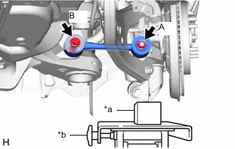
*a Wooden Block *b Transmission Jack Using a transmission jack and a wooden block, support the rear axle carrier sub-assembly.
-
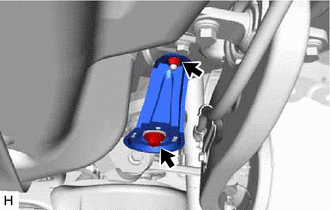
Remove the nut (A) and spacer.
-
Remove the bolt (B), nut and rear No. 1 suspension arm assembly from the rear axle carrier sub-assembly and rear suspension member sub-assembly.
Note
Because the nut has its own stopper, do not turn the nut. Loosen the bolt with the nut secured.
-
Temporarily install the rear lower suspension member stopper with the bolt and nut.
-
-
REMOVE REAR NO. 1 SUSPENSION ARM ASSEMBLY (for AWD)
-
*a Wooden Block *b Transmission Jack Using a transmission jack and a wooden block, support the rear differential carrier assembly.
Note
Keep supporting the rear differential carrier assembly with a transmission jack until the installation of the rear No. 1 suspension arm assembly has been completed.
-
Remove the bolt, nut and rear lower suspension member stopper.
-
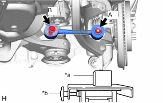
*a Wooden Block *b Transmission Jack Using a transmission jack and a wooden block, support the rear axle carrier sub-assembly.
-
Remove the nut (A) and spacer.
-
Remove the bolt (B), nut and rear No. 1 suspension arm assembly from the rear axle carrier sub-assembly and rear suspension member sub-assembly.
Note
Because the nut has its own stopper, do not turn the nut. Loosen the bolt with the nut secured.
-
Temporarily install the rear lower suspension member stopper with the bolt and nut.
-