ECD SYSTEM (w/o EGR Cooler), Diagnostic DTC:P0047, P0048
| DTC Code | DTC Name |
|---|---|
| P0047 | Turbocharger/Supercharger Boost Control "A" Circuit Low |
| P0048 | Turbocharger/Supercharger Boost Control "A" Circuit High |
DESCRIPTION
Refer to DTC P0046 Click here.
| DTC No. | DTC Detection Condition | Trouble Area |
|---|---|---|
| P0047 | All of following conditions met for 1 second or more (1 trip detection logic):
|
|
| P0048 | DC motor current 6.5 A or more for 0.5 seconds or more (1 trip detection logic) |
|
WIRING DIAGRAM
Refer to DTC P0046 Click here.
INSPECTION PROCEDURE
Note
After replacing the ECM, the new ECM needs registration Click here and initialization Click here.
Tech Tips
Read freeze frame data using the intelligent tester. Freeze frame data records the engine condition when malfunctions are detected. When troubleshooting, freeze frame data can help determine if the vehicle was moving or stationary, if the engine was warmed up or not, and other data from the time the malfunction occurred.
PROCEDURE
-
INSPECT TURBOCHARGER SUB-ASSEMBLY (DC MOTOR OPERATION)
-
Turn the ignition switch ON.
-
Turn the ignition switch OFF and check the DC motor operation.
OK When ignition switch is turned OFF, operation link moves as shown in A to D in illustration below. 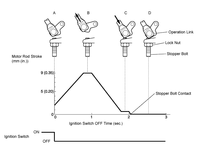
OK 
CHECK FOR INTERMITTENT PROBLEMS Click here
NG 
-
-
INSPECT TURBOCHARGER SUB-ASSEMBLY (DC MOTOR)
-
Disconnect the T10 DC motor connector.
-
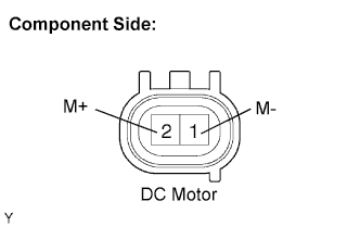
Measure the resistance of the DC motor.
Standard resistance Tester Connection Specified Condition M+ (2) - M- (1) 1 to 100 Ω
NG
REPLACE TURBOCHARGER SUB-ASSEMBLY Click here
OK
-
-
CHECK HARNESS AND CONNECTOR (DC MOTOR - TURBO MOTOR DRIVER)
-
Disconnect the T10 DC motor connector.
-
Disconnect the T8 turbo motor drive connector.
-
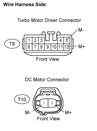
Measure the resistance of the wire harness side connectors.
Standard resistance (Check for open) Tester Connection Specified Condition M+ (T8-12) - M+ (T10-2) Below 1 Ω M- (T8-5) - M- (T10-1) Below 1 Ω Standard resistance (Check for short) Tester Connection Specified Condition M+ (T8-12) or M+ (T10-2) - Body ground 10 kΩ or higher M- (T8-5) or M- (T10-1) - Body ground 10 kΩ or higher
NG
REPAIR OR REPLACE HARNESS OR CONNECTOR
OK
-
-
REPLACE TURBO MOTOR DRIVER
NEXT
-
CHECK IF DTC OUTPUT RECURS (DTC P0047 AND/OR P0048)
-
Connect the intelligent tester to the DLC3.
-
Turn the ignition switch ON and turn the tester ON.
-
Clear the DTC Click here.
-
Start the engine.
-
Perform the test drive.
-
Enter the following menus: Powertrain / Engine and ECT / DTC.
-
Read the DTCs.
Result Display (DTC Output) Proceed to P0047 and/or P0048 A No output B
B
END
A 
REPLACE TURBOCHARGER SUB-ASSEMBLY Click here
-