REAR BRAKE INSTALLATION

-
TEMPORARILY TIGHTEN REAR DRUM BRAKE BLEEDER PLUG
-
INSTALL REAR WHEEL BRAKE CYLINDER CUP KIT
-
Apply the lithium soap base glycol grease to 2 new wheel cylinder cups and 2 pistons.
-
Install the 2 wheel cylinder cups on each piston.
-
Install the compression spring and the 2 pistons to the wheel brake cylinder assembly.
-
Install the 2 new cylinder dust boots to the wheel brake cylinder assembly.
-
-
INSTALL REAR WHEEL BRAKE CYLINDER ASSEMBLY
-
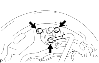
Install the wheel brake cylinder assembly with the 2 bolts.
- Torque:
- 9.5 N*m { 97 kgf*cm, 84 in.*lbf }
-
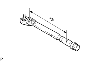
Text in Illustration *a Torque Wrench Fulcrum Length Using a union nut wrench, connect the brake tube.
- Torque:
- Specified tightening torque
- 15 N*m { 155 kgf*cm, 11 ft.*lbf }
Tech Tips
-
Calculate the torque wrench reading when changing the fulcrum length of the torque wrench Click here.
-
When using a union nut wrench (fulcrum length of 22 mm (0.8661 in.)) + torque wrench (fulcrum length of 162 mm (6.3779 in.)): 13 N*m (137 kgf*cm, 10 ft.*lbf)
-
-
APPLY HIGH TEMPERATURE GREASE
-
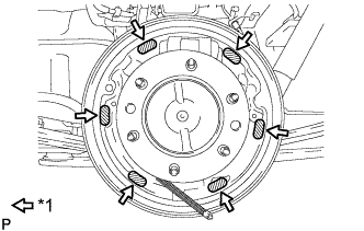
Text in Illustration *1 High temperature grease Apply high temperature grease to the shoe attached surface of the backing plate.
-
-
INSTALL PARKING BRAKE SHOE STRUT SET
-
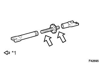
Text in Illustration *1 High temperature grease Apply the high temperature grease to the adjusting bolt.
-
Install the tension spring to the shoe strut set.
-
-
INSTALL REAR BRAKE SHOE
-
for 254 mm drum:
-
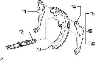
Text in Illustration *1 Brake Shoe Lever *2 Brake Shoe Strut Set *3 Rear Brake Shoe *4 Rear Cushion Lever *5 C-washer Using pliers, install the rear brake shoe, shoe strut set, rear cushion lever and shoe lever with a new C-washer.
-
Connect the parking brake cable No. 3 to the front brake shoe.
-
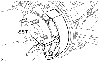
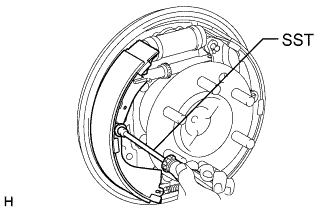
Using SST, install the rear brake shoe, pin, shoe hold down spring and shoe hold down cup.
- SST
- 09718-00011
-
-
for 295 mm drum:
-
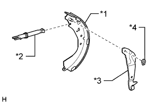
Text in Illustration *1 Rear Brake Shoe *2 Brake Shoe Strut Set *3 Brake Shoe Lever *4 C-washer Install the rear brake shoe, brake shoe strut set and shoe lever with a new C-washer.
-
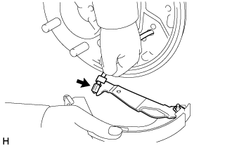
Connect the parking brake cable No. 3 to the front brake shoe.
-
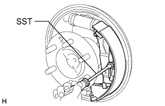
Using SST, install the rear brake shoe, pin, shoe hold down spring and shoe hold down cup.
- SST
- 09718-00011
-
-
-
INSTALL FRONT BRAKE SHOE
-
for 254 mm drum:
-
Install the return spring to each brake shoe.
-
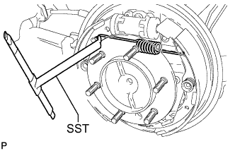
Using SST, install the front brake shoe, pin, shoe hold down spring and shoe hold down cup.
- SST
- 09718-00011
-
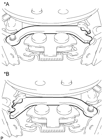
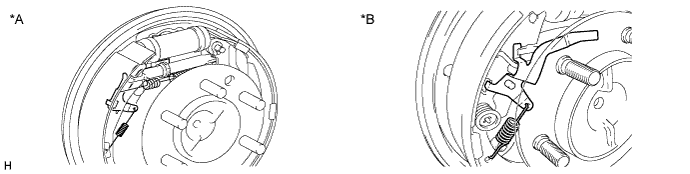
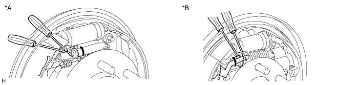
Text in Illustration *A LH Side *B RH Side Install the brake shoe lower strut.
Note
Make sure that the shoe lower strut and brake rear cushion lever are securely engaged.
-
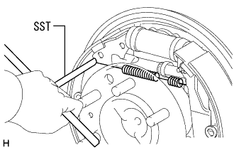
Using needle-nose pliers, install the tension spring.
-
-
for 295 mm drum:
-
Using SST, install the front brake shoe, pin, shoe hold down spring and shoe hold down cup.
- SST
- 09718-00011
-
Install the return spring to each brake shoe.
-
-
-
CONNECT PARKING BRAKE SHOE STRUT SET
-
for 254 mm drum:
-
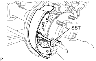
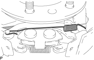
Using SST, install the upper side tension spring.
- SST
- 09703-30011
-
-
for 295 mm drum:
-
Using SST, install the upper side tension spring.
- SST
- 09703-30011
-
-
-
INSTALL AUTOMATIC ADJUST LEVER
-
Install the automatic adjust lever and tension spring.
Text in Illustration *A for 295 mm Drum *B for 254 mm Drum Note
Make sure to install the automatic adjust lever between the groove of the shoe strut set and brake shoe.
-
-
INSPECT REAR DRUM BRAKE
-
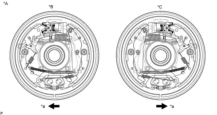
Check the each part is installed properly.
Text in Illustration *A for 254 mm Drum *B LH Side *C RH Side - - *a Front - - 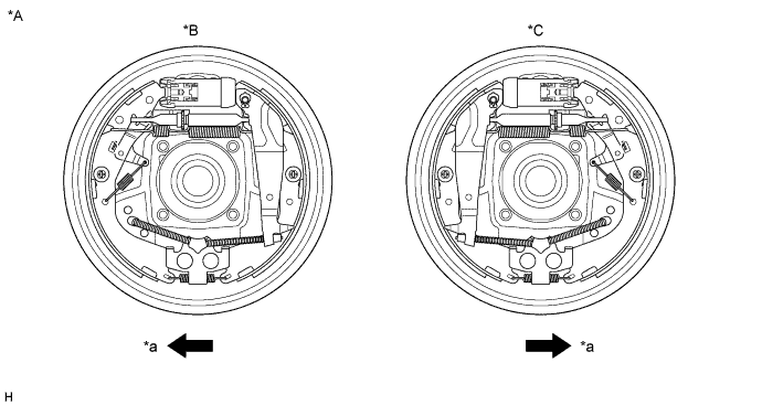
Text in Illustration *A for 295 mm Drum *B LH Side *C RH Side - - *a Front - - Note
There should be no oil or grease adhering to the friction surfaces of the shoe lining and drum.
-
If they are not installed correctly, reinstall them as shown in the illustration.
-
-
INSTALL REAR AXLE BRAKE DRUM GASKET
-
Install the new brake drum gasket to the rear axle shaft.
-
-
INSTALL REAR BRAKE DRUM SUB-ASSEMBLY
-
ADJUST REAR DRUM BRAKE SHOE CLEARANCE
-
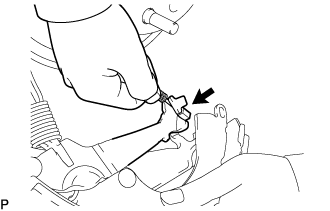
Using a screwdriver from a service hole, turn the adjuster to expand the shoes so that the brake shoes touch the brake drum.
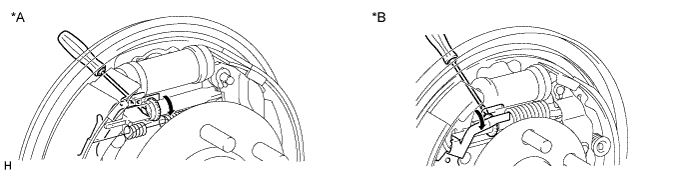
Text in Illustration *A for 295 mm Drum *B for 254 mm Drum -
Using another screwdriver, push up the automatic adjust lever and turn the adjuster to contract the shoes so that the brake shoe does not touch the brake drum. Then turn the adjuster another 180 degrees to further contract the shoes.
Text in Illustration *A for 295 mm Drum *B for 254 mm Drum -
Install the hole plug.
-
-
ADD BRAKE FLUID
Fluid SAE J1703 or FMVSS No. 116 DOT3 or equivalent Note
Do not remove the filter from the brake master cylinder reservoir and be sure to fill with new brake fluid to avoid any potential contamination of the brake system. Contamination, for example by dirt particles or mineral oil, could lead to functional brake problems.
-
BLEED BRAKE LINE
-
Connect the vinyl tube to the bleeder plug.
-
Depress the brake pedal several times and loosen the bleeder plug with the pedal held down.
-
At the point where the fluid stops coming out, tighten the bleeder plug and release the brake pedal.
-
Repeat this procedure until the air in the brake fluid is completely bled out.
-
Tighten the bleeder plug.
-
Front bleeder plug:
- Torque:
- 11 N*m { 110 kgf*cm, 8 ft.*lbf }
-
Rear bleeder plug:
- Torque:
- 11 N*m { 112 kgf*cm, 8 ft.*lbf }
-
-
Repeat the above procedure to bleed the air out of the brake line for each wheel.
-
-
INSPECT BRAKE FLUID LEVEL
-
Check the fluid level and add fluid if necessary.
Fluid SAE J1703 or FMVSS No.116 DOT3 or equivalent Note
Do not remove the filter from the brake master cylinder reservoir and be sure to fill with new brake fluid to avoid any potential contamination of the brake system. Contamination, for example by dirt particles or mineral oil, could lead to functional brake problems.
-
-
INSTALL REAR WHEEL
- Torque:
- 100 N*m { 1020 kgf*cm, 74 ft.*lbf }
-
INSPECT PARKING BRAKE CONTROL HANDLE TRAVEL
-
Pull firmly on the parking brake control handle.
-
Release the parking brake lock, and return the parking brake control handle to its off position.
-
Slowly pull the parking brake control handle all the way up, and count the number of clicks.
Parking brake control handle travel 10 to 16 clicks at 200 N (20 kgf, 44 lbf) (except Super Long Wheelbase) 12 to 18 clicks at 200 N (20 kgf, 44 lbf) (for Super Long Wheelbase) Tech Tips
-
If the number of clicks falls outside of the specified range, release the parking brake lock and adjust it.
-
If there are fewer clicks than the specified value, loosen the parking brake wire adjustment nut an the lock nut. With the parking brake cable loosened, adjust the clearance between the brake drum and lining.
-
-
-
ADJUST PARKING BRAKE CONTROL HANDLE TRAVEL
-
Lift the vehicle
-
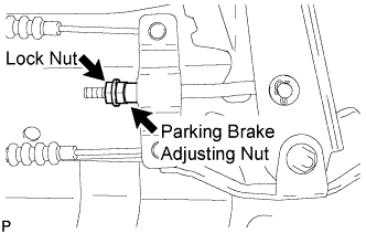
Depress the parking brake handle. Hold the parking brake adjusting nut using a wrench, and loosen the lock nut.
-
Turn the parking brake adjusting nut until the parking brake handle travel meets the above specification.
Parking brake control handle travel 10 to 16 clicks at 200 N (20 kgf, 44 lbf) (except Super Long Wheelbase) 12 to 18 clicks at 200 N (20 kgf, 44 lbf) (for Super Long Wheelbase) -
Count the number of clicks after depressing and releasing the parking brake control handle 3 or 4 times.
-
Check whether the parking brake drags or not.
-
When operating the parking brake control handle, check that the parking brake indicator light comes on.
Standard Brake warning light always comes on at the first click. -
Hold the parking brake adjusting nut using a wrench, and tighten the lock nut.
- Torque:
- 14.5 N*m { 148 kgf*cm, 11 ft.*lbf }
-
Lower the vehicle.
-