REAR TRAILING ARM REMOVAL
CAUTION / NOTICE / HINT
The necessary procedures (adjustment, calibration, initialization, or registration) that must be performed after parts are removed and installed, or replaced during rear trailing arm assembly removal/installation are shown below.
| Replaced Part or Performed Procedure | Necessary Procedure | Effect/Inoperative Function when Necessary Procedure not Performed | Link |
|---|---|---|---|
| Rear wheel alignment adjustment |
|
|
|
| Suspension, tires, etc. (The vehicle height changes because of suspension or tire replacement) |
|
|
|
| Rear television camera assembly optical axis (Back camera position setting) | Parking assist monitor system (w/ Parallel Parking Assist Function) | for Initialization: Click here for Calibration: Click here |
|
| Rear television camera assembly optical axis (Back camera position setting) | Parking assist monitor system (w/o Parallel Parking Assist Function) | for Initialization: Click here for Calibration: Click here |
|
|
Panoramic view monitor system | for Initialization: Click here for Calibration: Click here |
|
| Initialize headlight ECU sub-assembly LH |
|
Tech Tips
-
Use the same procedure for the RH side and LH side.
-
The following procedure is for the LH side.
PROCEDURE
-
REMOVE REAR WHEEL
-
REMOVE REAR SUSPENSION ARM COVER
-
SEPARATE NO. 2 PARKING BRAKE WIRE ASSEMBLY
-
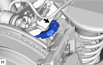
Disconnect the No. 2 parking brake wire assembly connector.
-
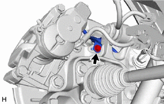
Remove the bolt and separate the No. 2 parking brake wire assembly from the rear axle carrier sub-assembly.
-
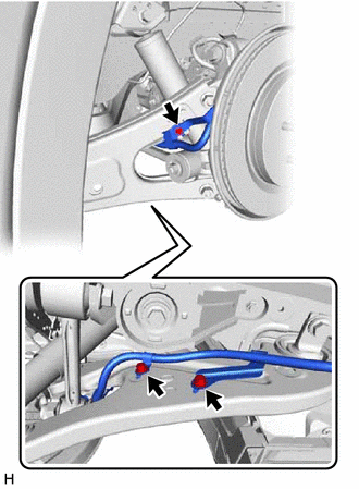
Remove the 3 bolts and separate the No. 2 parking brake wire assembly from the rear trailing arm assembly.
-
-
REMOVE PARKING BRAKE WIRE BRACKET (for 2WD)
-
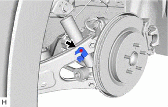
Remove the bolt and parking brake wire bracket from the rear trailing arm assembly.
-
-
SEPARATE REAR SPEED SENSOR (for AWD)
-
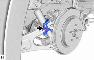
Remove the bolt and rear speed sensor from the rear trailing arm assembly.
-
-
REMOVE REAR TRAILING ARM ASSEMBLY
-
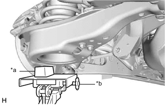
*a Wooden Block *b Transmission Jack Using a transmission jack and a wooden block, support the rear No. 2 suspension arm assembly.
Note
-
When jacking up the rear No. 2 suspension arm assembly, be sure to jack it up slowly.
-
Make sure to perform this operation with the vehicle kept as low as possible.
-
-
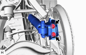
Remove the 2 bolts and separate the rear lower shock absorber bracket sub-assembly from the rear axle carrier sub-assembly.
-
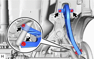
Remove the 4 bolts, 2 washers and rear trailing arm assembly.
-
Temporarily install the rear lower shock absorber bracket sub-assembly to the rear axle carrier sub-assembly with the 2 bolts.
-
Slowly lower the rear No. 2 suspension arm assembly.
-