ENGINE UNIT REASSEMBLY

CAUTION / NOTICE / HINT
Note
This procedure includes the installation of small-head bolts. Refer to Small-Head Bolts of Basic Repair Hint to identify the small-head bolts.
PROCEDURE
-
INSTALL RING PIN
Note
It is not necessary to remove a ring pin unless it is being replaced.
-
Using a plastic-faced hammer, tap in new ring pins to the camshaft housing sub-assembly.
Standard protrusion height 3.2 to 3.8 mm (0.125 to 0.149 in.) 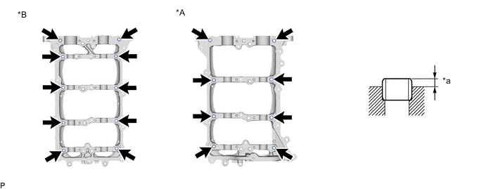
*A for Bank 2 *B for Bank 1 *a Protrusion Height - -
-
-
INSTALL CYLINDER BLOCK WATER JACKET SPACER
-

Front Side Install the 2 cylinder block water jacket spacers as shown in the illustration.
-
-
INSTALL NO. 1 OIL PIPE
-
Install the No. 1 oil pipe and PCV pipe with the bolt.
- Torque:
- 21 N*m { 214 kgf*cm, 15 ft.*lbf }
-
-
INSTALL NO. 1 PCV CASE
-
Install a new gasket to the No. 1 PCV case.
Note
Check that the gasket is securely fitted into the installation groove.
-
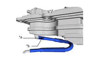
*a Protrusion *b Paint mark Connect the PCV pipe to the No. 1 PCV case.
Tech Tips
Align the protrusion of the No. 1 PCV case with the paint mark of the PCV hose.
-
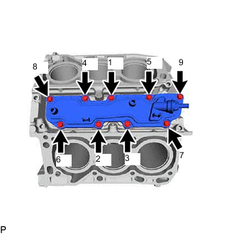
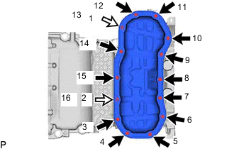
Install the No. 1 PCV case with the 9 bolts in the order shown in the illustration.
- Torque:
- 21 N*m { 214 kgf*cm, 15 ft.*lbf }
-
-
INSTALL KNOCK CONTROL SENSOR
-
INSTALL SENSOR WIRE
-
Install the sensor wire with the 2 connectors and 2 clamps.
-
-
INSTALL CYLINDER HEAD GASKET LH
-
INSTALL CYLINDER HEAD SUB-ASSEMBLY LH
-
INSTALL CYLINDER HEAD GASKET RH
-
INSTALL CYLINDER HEAD SUB-ASSEMBLY RH
-
INSTALL VALVE STEM CAP
-
INSTALL VALVE LASH ADJUSTER ASSEMBLY
-
INSTALL VALVE ROCKER ARM SUB-ASSEMBLY
-
INSTALL CAMSHAFT HOUSING SUB-ASSEMBLY LH
-
INSTALL INTAKE CAMSHAFT SUB-ASSEMBLY LH
-
INSTALL EXHAUST CAMSHAFT SUB-ASSEMBLY LH
-
INSTALL NO. 3 CHAIN TENSIONER ASSEMBLY
-
Install the No. 3 chain tensioner assembly with the 2 bolts.
- Torque:
- 10 N*m { 102 kgf*cm, 7 ft.*lbf }
-
-
INSTALL CAMSHAFT BEARING CAP (for Bank 2)
-
INSTALL CAMSHAFT HOUSING SUB-ASSEMBLY RH
-
INSTALL INTAKE CAMSHAFT SUB-ASSEMBLY RH
-
INSTALL EXHAUST CAMSHAFT SUB-ASSEMBLY RH
-
INSTALL NO. 2 CHAIN TENSIONER ASSEMBLY
-
Install the No. 2 chain tensioner assembly with the 2 bolts.
- Torque:
- 10 N*m { 102 kgf*cm, 7 ft.*lbf }
-
-
INSTALL CAMSHAFT BEARING CAP (for Bank 1)
-
INSTALL REAR ENGINE OIL SEAL
-
Place the rear engine oil seal retainer on wooden blocks.
-
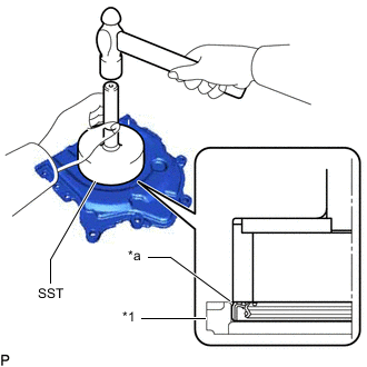
*1 Rear Engine Oil Seal Retainer *a 0 to 0.5 mm (-0 to 0.0197 in.) Using SST, tap in a new rear engine oil seal until its surface is flush with the rear engine oil seal retainer edge.
- SST
- 09223-56010
Oil Seal Protrusion Height 0 to 0.5 mm (-0 to 0.0197 in.) Note
-
Keep the lip free of foreign matter.
-
Do not tap on the rear engine oil seal at an angle.
-
-
INSTALL REAR ENGINE OIL SEAL RETAINER
-
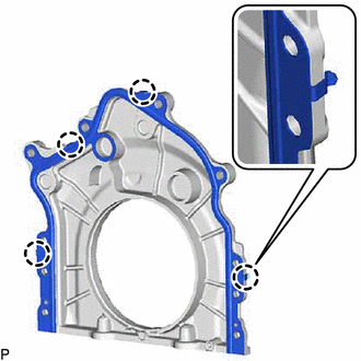
Install a new gasket as shown in the illustration.
Note
The claws of the gasket must face the rear engine oil seal retainer.
-
Apply MP grease to the lip of the rear engine oil seal.
-
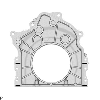

Seal Packing Apply seal packing in a continuous line as shown in the illustration.
Seal packing Toyota Genuine Seal Packing Black, Three Bond 1207B or equivalent Seal diameter 2.0 to 8.0 mm (0.0787 to 0.315 in.) Note
-
Remove any oil from the contact surface.
-
Install the rear engine oil seal retainer within 3 minutes after applying seal packing.
-
Do not start the engine for at least 2 hours after installation.
-
-
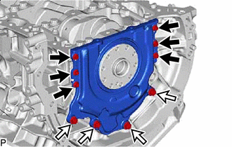
Bolt A (Do not reuse) 
Bolt B Install the rear engine oil seal retainer with the new 6 bolts and 4 bolts.
- Torque:
- for bolt A
- 10 N*m { 102 kgf*cm, 7 ft.*lbf }
- for bolt B
- 28 N*m { 286 kgf*cm, 21 ft.*lbf }
-
-
INSTALL NO. 1 OIL PAN BAFFLE PLATE
-
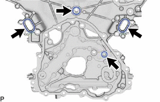
Temporarily install the No. 1 oil pan baffle plate with the 4 bolts.
Tech Tips
After temporarily installing the 4 bolts, install the oil strainer sub-assembly.
-
-
INSTALL OIL STRAINER SUB-ASSEMBLY
-
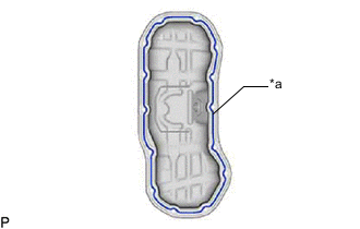
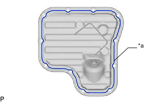
Install a new gasket with the oil strainer sub-assembly.
Note
Check that the gasket is securely fitted into the installation groove.
-
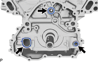
Temporarily install the oil strainer sub-assembly to the crankshaft bearing cap sub-assembly with the 3 bolts.
-
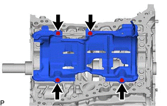
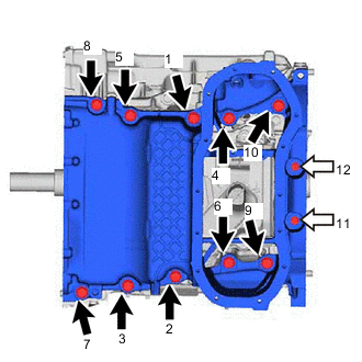
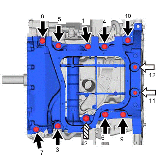
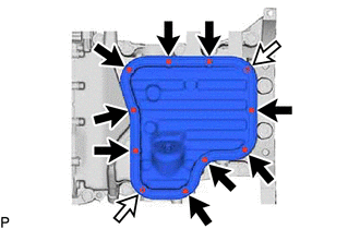
Tighten the 7 bolts in the order shown in the illustration.
- Torque:
- 10 N*m { 102 kgf*cm, 7 ft.*lbf }
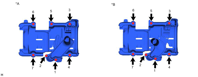
*A for 2WD *B for AWD -
Connect the PCV pipe clamp to the No. 1 oil pan baffle plate.
-
-
INSTALL NO. 1 OIL PAN SUB-ASSEMBLY
-
Remove any remaining seal packing material and be careful not to drop any oil on the contact surfaces of the No. 1 oil pan sub-assembly and crankshaft bearing cap sub-assembly.
-
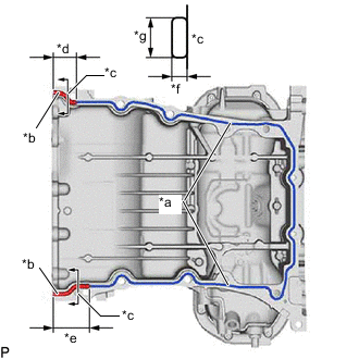
*a Standard Seal Packing Diameter
3.0 to 4.0 mm (0.118 to 0.157 in.)
*b Wide Seal Packing Diameter
5.5 to 6.5 mm (0.216 to 0.255 in.)
*c Thick Coating Cross-section *d Seal Packing Width 38 mm (1.49 in.) *e Seal Packing Width 60 mm (2.36 in.) *f 3.0 mm (0.118 in.) or more *g 8.0 to 12 mm (0.315 to 0.472 in.) for 2WD:
Apply seal packing in a continuous line as shown in the illustration.
Seal packing Toyota Genuine Seal Packing Black, Three Bond 1207B or equivalent Note
-
Remove any oil from the contact surface.
-
Install the No. 1 oil pan sub-assembly within 3 minutes after applying seal packing.
-
-
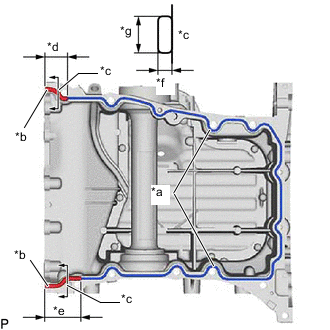
*a Standard Seal Packing Diameter
3.0 to 4.0 mm (0.118 to 0.157 in.)
*b Wide Seal Packing Diameter
5.5 to 6.5 mm (0.216 to 0.255 in.)
*c Thick Coating Cross-section *d Seal Packing Width 38 mm (1.49 in.) *e Seal Packing Width 60 mm (2.36 in.) *f 3.0 mm (0.118 in.) or more *g 8.0 to 12 mm (0.315 to 0.472 in.) for AWD:
Apply seal packing in a continuous line as shown in the illustration.
Seal packing Toyota Genuine Seal Packing Black, Three Bond 1207B or equivalent Note
-
Remove any oil from the contact surface.
-
Install the No. 1 oil pan sub-assembly within 3 minutes after applying seal packing.
-
-
Bolt A Bolt B for 2WD:
Install the No. 1 oil pan sub-assembly with the 12 bolts. Tighten the bolts uniformly in several steps.
- Torque:
- for bolt A
- 43 N*m { 438 kgf*cm, 32 ft.*lbf }
- for bolt B
- 10 N*m { 102 kgf*cm, 7 ft.*lbf }
Standard Bolt Item Length Bolt A 30 mm (1.18 in.) Bolt B 92 mm (3.62 in.) -
Bolt A Bolt B 
Bolt C for AWD:
Install the No. 1 oil pan sub-assembly with the 12 bolts. Tighten the bolts uniformly in several steps.
- Torque:
- for bolt A and C
- 43 N*m { 438 kgf*cm, 32 ft.*lbf }
- for bolt B
- 10 N*m { 102 kgf*cm, 7 ft.*lbf }
Standard Bolt Item Length Bolt A 30 mm (1.18 in.) Bolt B 92 mm (3.62 in.) Bolt C 90 mm (3.54 in.)
-
-
INSTALL ENGINE OIL LEVEL SENSOR
-
INSTALL NO. 2 OIL PAN SUB-ASSEMBLY
-
*a 3.0 to 4.0 mm (0.118 to 0.157 in.) Seal Packing for 2WD:
Apply seal packing in a continuous line as shown in the illustration.
Seal packing Toyota Genuine Seal Packing Black, Three Bond 1207B or equivalent Standard seal diameter 3.0 to 4.0 mm (0.118 to 0.157 in.) Note
-
Remove any oil from the contact surface.
-
Install the No. 2 oil pan sub-assembly within 3 minutes after applying seal packing.
-
-
*a 3.0 to 4.0 mm (0.118 to 0.157 in.) Seal Packing for AWD:
Apply seal packing in a continuous line as shown in the illustration.
Seal packing Toyota Genuine Seal Packing Black, Three Bond 1207B or equivalent Standard seal diameter 3.0 to 4.0 mm (0.118 to 0.157 in.) Note
-
Remove any oil from the contact surface.
-
Install the No. 2 oil pan sub-assembly within 3 minutes after applying seal packing.
-
-
Bolt Nut for 2WD:
Install the No. 2 oil pan sub-assembly with the 12 bolts and 2 nuts. Tighten the bolts and nuts uniformly in several steps.
- Torque:
- 16 N*m { 163 kgf*cm, 12 ft.*lbf }
Note
-
Tighten the nuts first. After tightening the bolts, check that the nuts and bolts are tightened to the specified torque.
-
Do not start the engine for at least 2 hours after the installation.
-
Bolt Nut for AWD:
Install the No. 2 oil pan sub-assembly with the 9 bolts and 2 nuts. Tighten the bolts and nuts uniformly in several steps.
- Torque:
- 16 N*m { 163 kgf*cm, 12 ft.*lbf }
Note
-
Tighten the nuts first. After tightening the bolts, check that the nuts and bolts are tightened to the specified torque.
-
Do not start the engine for at least 2 hours after the installation.
-
-
INSTALL OIL PAN DRAIN PLUG
-
Install a new gasket and the oil pan drain plug.
- Torque:
- 40 N*m { 408 kgf*cm, 30 ft.*lbf }
-
-
INSTALL NO. 6 ENGINE COVER
-
Install the No. 6 engine cover to the cylinder block sub-assembly.
-
-
INSTALL TIMING CHAIN COVER ASSEMBLY
-
Remove any remaining seal packing material and be careful not to drop any oil on the contact surfaces of the timing chain cover assembly and cylinder block sub-assembly and cylinder head sub-assembly.
-
CylinderBlock Sub-assembly Side:
Install 3 new oil pump gaskets to the cylinder block sub-assembly.
-
Timing Chain Cover Assembly Side:
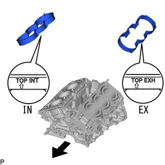
Install 2 new oil pump gaskets and 2 new water pump gaskets to the timing chain cover assembly.
-
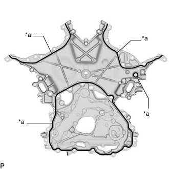
*a 3.0 to 3.5 mm (0.118 to 0.137 in.) Seal Packing Apply seal packing in a continuous line to the engine unit as shown in the illustration.
Seal packing Toyota Genuine Seal Packing Black, Three Bond 1207B or equivalent Seal diameter 3.0 to 3.5 mm (0.118 to 0.137 in.) Note
-
When the contact surfaces are wet, wipe them with an oil-free cloth before applying seal packing.
-
Install the timing chain cover assembly within 3 minutes and tighten the bolts within 10 minutes after applying seal packing.
-
-
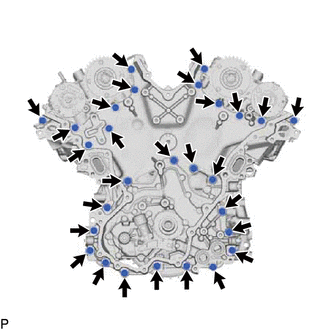
Temporarily install the timing chain cover assembly with the 28 bolts.
Note
Make sure that there is no oil on the bolt threads.
-
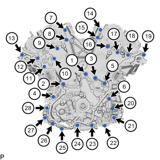
Tighten the bolts in the order shown in the illustration.
- Torque:
- 21 N*m { 214 kgf*cm, 15 ft.*lbf }
Note
-
Do not start the engine for at least 2 hours after installation.
-
Wipe off any seal packing that seeped out around the surfaces of the No. 1 oil pan sub-assembly and cylinder head cover sub-assembly and make sure that there is no seal packing seeping out around the edges.
-
-
INSTALL CRANKSHAFT TIMING GEAR OR SPROCKET
-
Install the 2 timing gear set keys and camshaft timing gear or sprocket to the crankshaft.
-
-
INSTALL NO. 2 CHAIN VIBRATION DAMPER
-
Install the 2 No. 2 chain vibration dampers with the 4 bolts.
- Torque:
- 21 N*m { 214 kgf*cm, 15 ft.*lbf }
-
-
INSTALL NO. 1 CHAIN VIBRATION DAMPER
-
Install the No. 1 chain vibration damper with the 2 bolts.
- Torque:
- 21 N*m { 214 kgf*cm, 15 ft.*lbf }
-
-
INSTALL IDLE SPROCKET ASSEMBLY
-
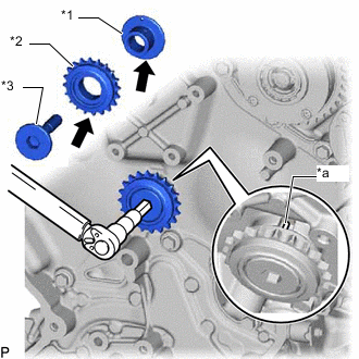
*1 No. 1 Idle Gear Shaft *2 Idle Sprocket *3 No. 2 Idle Gear Shaft *a Knock Pin Apply Engine Oil Apply a light coat of engine oil to the rotating surface of the No. 1 idle gear shaft.
-
Temporarily install the No. 1 idle gear shaft and idle sprocket with the No. 2 idle gear shaft while aligning the knock pin of the No. 1 idle gear with the knock pin groove of the cylinder block sub-assembly.
Note
Make sure that the idle gear is facing the correct direction.
Tech Tips
Check that no foreign objects are on the No. 1 and No. 2 idle gear shafts.
-
Using a 10 mm hexagon wrench, tighten the No. 2 idle gear shaft.
- Torque:
- 56 N*m { 571 kgf*cm, 41 ft.*lbf }
Tech Tips
After installing the idle sprocket assembly, check that the idle sprocket turns smoothly.
-
-
INSTALL NO. 1 CHAIN SUB-ASSEMBLY
-
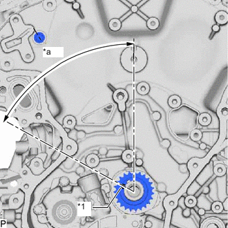
*1 Crankshaft Pulley Set Key *a 60° Turn the crankshaft 60° counterclockwise and set it as shown in the illustration.
-
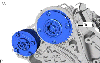
*A for Bank 1 *a Timing Mark Check that the camshaft timing gear position on the bank 1 as shown in the illustration.
-
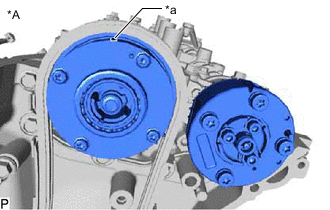
*A for Bank 2 *a Timing Mark Check that the camshaft timing gear position on the bank 2 as shown in the illustration.
-
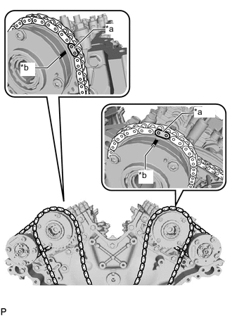
*a Mark Plate (Pink) *b Timing Mark Align the mark plates and timing marks as shown in the illustration and install the No. 1 chain sub-assembly.
Tech Tips
The camshaft mark plates are pink.
-
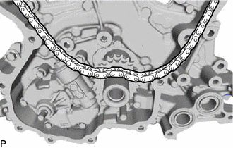
Rest the No. 1 chain sub-assembly on top of the crankshaft.
-
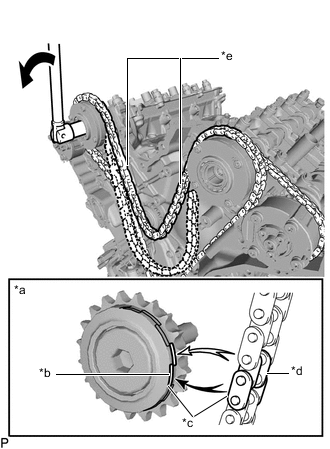
*a When idle sprocket is reused *b Mark *c Align *d Chain Plate *e Chain sub-assembly between the banks Turn Turn the camshaft timing gear assembly on the RH bank counterclockwise to tighten the chain sub-assembly between the banks.
Note
When the idle sprocket is reused, align the chain plate with the mark where the plate had been in order to tighten the chain sub-assembly between the banks.
-
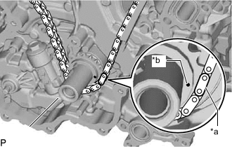
*a Mark Plate (Orange) *b Timing Mark Align the mark plate and timing mark as shown in the illustration and install the No. 1 chain sub-assembly onto the crankshaft timing sprocket.
Tech Tips
The crankshaft mark plate is orange.
-
Temporarily install the crankshaft pulley set bolt.
-
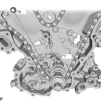
*1 Crankshaft Pulley Set Key *a Center Line Turn the crankshaft clockwise to set it to the block bore center line RH (TDC/compression).
-
-
INSTALL CHAIN TENSIONER SLIPPER
-
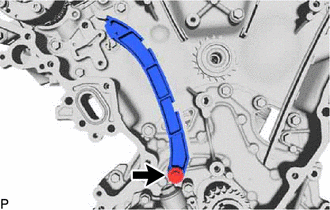
Install the chain tensioner slipper with the bolt.
- Torque:
- 21 N*m { 214 kgf*cm, 15 ft.*lbf }
-
-
INSTALL NO. 1 CHAIN TENSIONER ASSEMBLY
-
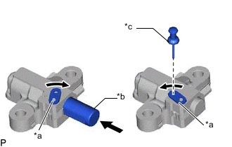
*a Stopper Plate *b Plunger *c Pin Move the stopper plate upward to release the lock, and push the plunger deep into the No. 1 chain tensioner assembly.
-
Move the stopper plate downward to set the lock, and insert a pin of 1.27 mm (0.0500 in.) diameter into the hole of the stopper plate.
-
Install the new gasket to the No. 1 chain tensioner assembly.
-
Install the No. 1 chain tensioner assembly with the 2 bolts.
- Torque:
- 21 N*m { 214 kgf*cm, 15 ft.*lbf }
-
Remove the lock pin of the No. 1 chain tensioner assembly.
-
-
INSPECT VALVE TIMING
-
Check the camshaft timing marks.
Note
-
Check each timing mark from a viewpoint directly inline with the center of the camshaft and the timing mark on each camshaft timing gear.
-
If the timing marks are checked from any other viewpoint, the valve timing may appear misaligned.
-
-
for Bank 1 side:
Check that each camshaft timing mark is positioned as shown in the illustration.
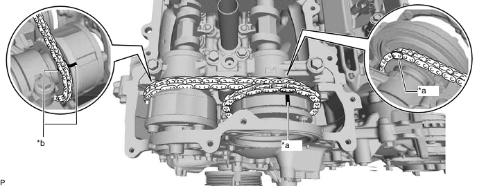
*a Timing Mark (Camshaft Timing Intake Gear Assembly Side) *b Timing Mark (Camshaft Timing Exhaust Gear Assembly Side) -
for Bank 2 side:
Check that each camshaft timing mark is positioned as shown in the illustration.
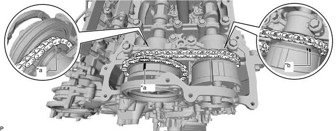
*a Timing Mark (Camshaft Timing Intake Gear Assembly Side) *b Timing Mark (Camshaft Timing Exhaust Gear Assembly Side) -
If the valve timing is misaligned, reinstall the timing chain.
-
Remove the crankshaft pulley set bolt.
-
-
INSTALL OIL PUMP DRIVE CHAIN SUB-ASSEMBLY
-
INSTALL ENGINE WATER PUMP ASSEMBLY
-
INSTALL TIMING CHAIN OR BELT COVER SUB-ASSEMBLY
-
INSTALL TIMING CHAIN CASE OIL SEAL
-
INSTALL CRANKSHAFT PULLEY
-
INSTALL CRANKSHAFT DAMPER SUB-ASSEMBLY
-
INSTALL CRANKSHAFT PULLEY COVER
-
INSTALL OIL FILTER BRACKET SUB-ASSEMBLY
-
INSTALL ENGINE OIL PRESSURE SWITCH ASSEMBLY
-
INSTALL GENERATOR BRACKET SUB-ASSEMBLY
-
Install the generator bracket sub-assembly with the 4 bolts.
- Torque:
- 43 N*m { 438 kgf*cm, 32 ft.*lbf }
-
-
DISCONNECT NO. 1 WATER BY-PASS PIPE
-
INSTALL WATER INLET ASSEMBLY
-
Install a new water inlet pipe gasket to the water inlet assembly.
-
Install the water inlet assembly with the 3 bolts.
- Torque:
- 10 N*m { 102 kgf*cm, 7 ft.*lbf }
-
-
INSTALL ENGINE COOLANT TEMPERATURE SENSOR
-
INSTALL CRANKSHAFT POSITION SENSOR
-
INSTALL VACUUM PUMP ASSEMBLY
-
INSTALL SPARK PLUG TUBE GASKET
-
Install 6 new spark plug tube gaskets to the cylinder head cover sub-assembly.
-
-
INSTALL CYLINDER HEAD COVER SUB-ASSEMBLY RH
-
INSTALL CYLINDER HEAD COVER SUB-ASSEMBLY LH
-
INSTALL CAM TIMING CONTROL MOTOR WITH EDU ASSEMBLY LH
-
INSTALL CAM TIMING CONTROL MOTOR WITH EDU ASSEMBLY RH
-
INSTALL CAM TIMING OIL CONTROL SOLENOID ASSEMBLY LH
-
INSTALL CAM TIMING OIL CONTROL SOLENOID ASSEMBLY RH
-
INSTALL NO. 2 ENGINE COVER RH
-
Install the No. 2 engine cover RH to the cylinder head cover sub-assembly RH.
-
-
INSTALL NO. 2 ENGINE COVER LH
-
Install the No. 2 engine cover LH to the cylinder head cover sub-assembly LH.
-
-
INSTALL SPARK PLUG
-
INSTALL NO. 2 FUEL DELIVERY PIPE SUB-ASSEMBLY LH
-
INSTALL NO. 2 FUEL DELIVERY PIPE SUB-ASSEMBLY RH
-
INSTALL NO. 3 FUEL PIPE SUB-ASSEMBLY
-
INSTALL LOWER INTAKE MANIFOLD SUB-ASSEMBLY
-
INSTALL FUEL VAPOR FEED PIPE SUB-ASSEMBLY
-
INSTALL NO. 2 MANIFOLD STAY
-
INSTALL NO. 1 FUEL DELIVERY PIPE SUB-ASSEMBLY LH
-
INSTALL NO. 1 FUEL DELIVERY PIPE SUB-ASSEMBLY RH