СИСТЕМА ЗАРЯДКИ ДВИГАТЕЛЯ, Diagnostic DTC:P1602
| DTC Code | DTC Name |
|---|---|
| P1602 | Deterioration of Battery |
DESCRIPTION
The battery state sensor assembly detects the battery voltage. When the engine is running, the battery state sensor assembly determines the battery status based on the detected voltage and sends this information to the engine control ECU. If the engine control ECU judges that the battery has deteriorated based on the signal received, it stores this DTC.
| DTC No. | Detection Item | DTC Detection Condition | Trouble Area | Warning Indicate | Memory |
|---|---|---|---|---|---|
| P1602 | Deterioration of Battery | Battery voltage is low for 10 seconds or more when the engine is running (not cranking). (1 trip detection logic) |
|
Charge warning light does not come on | DTC stored |
CAUTION / NOTICE / HINT
Note
-
Inspect the fuses for circuits related to this system before performing the following inspection procedure.
-
When P058A (Battery Monitor Module Performance) is output at the same time, perform the inspection for P058A01 (Battery Monitor Module Performance) first.
-
When P162B (Lost Communication with Battery Monitor Module) is output at the same time, perform the inspection for P162B (Lost Communication with Battery Monitor Module) first.
PROCEDURE
-
CHECK BATTERY STATE SENSOR ASSEMBLY INSTALLATION CONDITION
-
Check installation condition of the battery state sensor assembly.
Result Result OK NG
NG 
INSTALL THE BATTERY STATE SENSOR ASSEMBLY CORRECTLY Click here
OK 
-
-
CHECK CHARGING SYSTEM
-
Check the charging system.
Result Result OK NG
NG
REPAIR OR REPLACE CHARGING SYSTEM
OK
-
-
CHECK HARNESS AND CONNECTOR (POWER SOURCE CIRCUIT)
-
Check that the battery state sensor assembly connector is securely connected.
OK The connector is securely connected. -
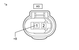
*a Front view of wire harness connector
(to Battery State Sensor Assembly)
Disconnect the A5 battery state sensor assembly connector.
-
Check the connector case and terminals for deformation or corrosion.
OK No deformation or corrosion. -
Measure the voltage according to the value(s) in the table below.
Standard Voltage Tester Connection Condition Specified Condition A5-1 (+B) - Body ground Always 11 to 14 V Result Result OK NG
OK
CHECK FOR INTERMITTENT PROBLEMS Click here
NG
REPAIR OR REPLACE HARNESS OR CONNECTOR
-