LIGHTING SYSTEM Outside Handle Foot Light Circuit
DESCRIPTION
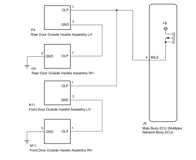
The main body ECU (multiplex network body ECU) controls the outside handle foot lights.
WIRING DIAGRAM
CAUTION / NOTICE / HINT
Note
-
Before replacing the main body ECU (multiplex network body ECU), refer to Service Bulletin.
-
The vehicle battery supplies power to the main body ECU (multiplex network body ECU) via the door control battery. Therefore, before proceeding with troubleshooting, perform an on-vehicle inspection and confirm that the main body ECU (multiplex network body ECU) power source circuit is normal.*
-
*: w/o Canister Pump Module with Door Ajar Warning Buzzer Function
PROCEDURE
-
PERFORM ACTIVE TEST USING GTS
-
Connect the GTS to the DLC3.
-
Turn the engine switch on (IG).
-
Turn the GTS on.
-
Enter the following menus: Body Electrical / Main Body / Active Test.
-
Perform the Active Test according to the display on the GTS.
Body Electrical > Main Body > Active TestTester Display Measurement Item Control Range Diagnostic Note Exterior Light Outside handle foot lights ON/OFF -
Body Electrical > Main Body > Active TestTester Display Exterior Light OK Outside handle foot lights illuminate. Result Result Proceed to OK A NG (for Front Side) B NG (for Rear Side) C
A 
PROCEED TO NEXT SUSPECTED AREA SHOWN IN PROBLEM SYMPTOMS TABLE Click here
C 
CHECK REAR DOOR OUTSIDE HANDLE ASSEMBLY LH Click here
B 
-
-
CHECK FRONT DOOR OUTSIDE HANDLE ASSEMBLY LH
-
Disconnect the N11 front door outside handle assembly LH connector.
-
Measure the voltage according to the value(s) in the table below.
Standard Voltage Tester Connection Condition Specified Condition N11-1 (OLP) - Body ground Illumination conditions of outside handle foot lights met* 11 to 14 V
-
*: Refer to System Description for the illumination conditions of the outside handle foot lights.
Result Proceed to OK NG -
NG
REPAIR OR REPLACE HARNESS OR CONNECTOR
OK
-
-
INSPECT FRONT DOOR OUTSIDE HANDLE ASSEMBLY LH
-
Remove the front door outside handle assembly LH.
-
Inspect the front door outside handle assembly LH.
OK Outside handle foot light illuminates. Result Proceed to OK NG
NG
REPLACE FRONT DOOR OUTSIDE HANDLE ASSEMBLY LH Click here
OK
-
-
INSPECT FRONT DOOR OUTSIDE HANDLE ASSEMBLY RH
-
Remove the front door outside handle assembly RH.
-
Inspect the front door outside handle assembly RH.
OK Outside handle foot light illuminates. Result Proceed to OK NG
NG
REPLACE FRONT DOOR OUTSIDE HANDLE ASSEMBLY RH Click here
OK
-
-
CHECK HARNESS AND CONNECTOR (FRONT DOOR OUTSIDE HANDLE ASSEMBLY RH - BODY GROUND)
-
Measure the resistance according to the value(s) in the table below.
Standard Resistance Tester Connection Condition Specified Condition M11-3 (GND) - Body ground Always Below 1 Ω Result Proceed to OK NG
OK
REPAIR OR REPLACE HARNESS OR CONNECTOR (FRONT DOOR OUTSIDE HANDLE ASSEMBLY LH - FRONT DOOR OUTSIDE HANDLE ASSEMBLY RH)
NG
REPAIR OR REPLACE HARNESS OR CONNECTOR
-
-
CHECK REAR DOOR OUTSIDE HANDLE ASSEMBLY LH
-
Disconnect the P4 rear door outside handle assembly LH connector.
-
Measure the voltage according to the value(s) in the table below.
Standard Voltage Tester Connection Condition Specified Condition P4-1 (OLP) - Body ground Illumination conditions of outside handle foot lights met* 11 to 14 V
-
*: Refer to System Description for the illumination conditions of the outside handle foot lights.
Result Proceed to OK NG -
NG
REPAIR OR REPLACE HARNESS OR CONNECTOR
OK
-
-
INSPECT REAR DOOR OUTSIDE HANDLE ASSEMBLY LH
-
Remove the rear door outside handle assembly LH.
-
Inspect the rear door outside handle assembly LH.
OK Outside handle foot light illuminates. Result Proceed to OK NG
NG
REPLACE REAR DOOR OUTSIDE HANDLE ASSEMBLY LH Click here
OK
-
-
INSPECT REAR DOOR OUTSIDE HANDLE ASSEMBLY RH
-
Remove the rear door outside handle assembly RH.
-
Inspect the rear door outside handle assembly RH.
OK Outside handle foot light illuminates. Result Proceed to OK NG
NG
REPLACE REAR DOOR OUTSIDE HANDLE ASSEMBLY RH Click here
OK
-
-
CHECK HARNESS AND CONNECTOR (REAR DOOR OUTSIDE HANDLE ASSEMBLY RH - BODY GROUND)
-
Measure the resistance according to the value(s) in the table below.
Standard Resistance Tester Connection Condition Specified Condition O4-3 (GND) - Body ground Always Below 1 Ω Result Proceed to OK NG
OK
REPAIR OR REPLACE HARNESS OR CONNECTOR (REAR DOOR OUTSIDE HANDLE ASSEMBLY LH - REAR DOOR OUTSIDE HANDLE ASSEMBLY RH)
NG
REPAIR OR REPLACE HARNESS OR CONNECTOR
-