CAN COMMUNICATION SYSTEM (w/ VSC) ECM Communication Stop Mode
DESCRIPTION
| Detection Item | Symptom | Trouble Area |
|---|---|---|
| ECM Communication Stop Mode | When either condition below is met:
|
|
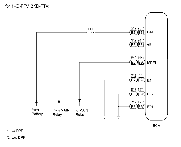
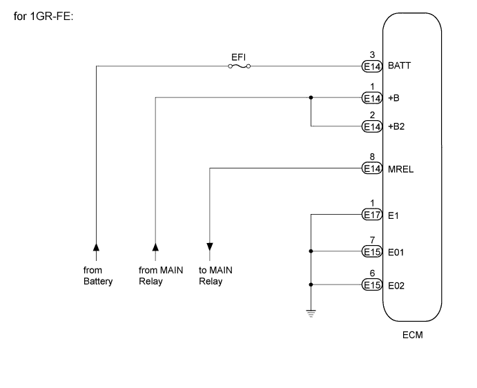
WIRING DIAGRAM
INSPECTION PROCEDURE
Tech Tips
Operating the ignition switch, any switches or any doors triggers related ECU and sensor communication with the CAN, which causes resistance variation.
PROCEDURE
-
CHECK HARNESS AND CONNECTOR (ECM - BATTERY AND BODY GROUND)
-
for 1KD-FTV, 2KD-FTV (w/ DPF):
-
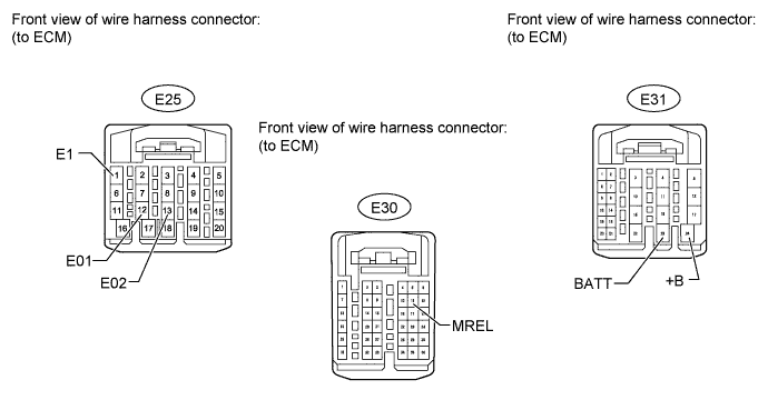
Disconnect the E25, E30 and E31 ECM connectors.
-
Measure the voltage according to the value(s) in the table below.
Standard Voltage Tester Connection Switch Condition Specified Condition E31-24 (+B) - Body ground When battery's positive (+) voltage is applied to terminal E30-11 (MREL) 11 to 14 V E31-23 (BATT) - Body ground Always 11 to 14 V -
Measure the resistance according to the value(s) in the table below.
Standard Resistance Tester Connection Condition Specified Condition E25-1 (E1) - Body ground Always Below 1 Ω E25-13 (E02) - Body ground Always Below 1 Ω E25-12 (E01) - Body ground Always Below 1 Ω
-
-
for 1KD-FTV, 2KD-FTV (w/o DPF):
-
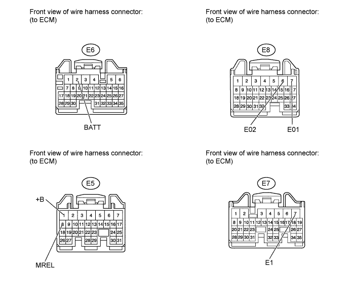
Disconnect the E5, E6, E7 and E8 ECM connectors.
-
Measure the voltage according to the value(s) in the table below.
Standard Voltage Tester Connection Switch Condition Specified Condition E5-1 (+B) - Body ground When battery's positive (+) voltage is applied to terminal E5-8 (MREL) 11 to 14 V E6-2 (BATT) - Body ground Always 11 to 14 V -
Measure the resistance according to the value(s) in the table below.
Standard Resistance Tester Connection Condition Specified Condition E7-7 (E1) - Body ground Always Below 1 Ω E8-6 (E02) - Body ground Always Below 1 Ω E8-7 (E01) - Body ground Always Below 1 Ω
-
-
for 1GR-FE:
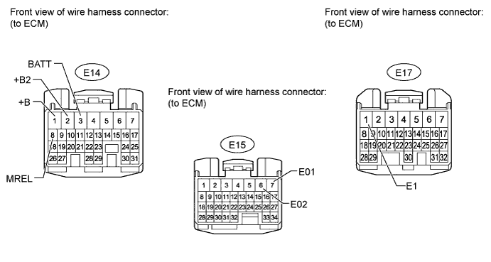
-
Disconnect the E14, E15 and E17 ECM connectors.
-
Measure the voltage according to the value(s) in the table below.
Standard Voltage Tester Connection Switch Condition Specified Condition E14-1 (+B) - Body ground When battery's positive (+) voltage is applied to terminal E14-8 (MREL) 11 to 14 V E14-2 (+B2) - Body ground When battery's positive (+) voltage is applied to terminal E14-8 (MREL) 11 to 14 V E14-3 (BATT) - Body ground Always 11 to 14 V -
Measure the resistance according to the value(s) in the table below.
Standard Resistance Tester Connection Condition Specified Condition E17-1 (E1) - Body ground Always Below 1 Ω E15-7 (E01) - Body ground Always Below 1 Ω E15-6 (E02) - Body ground Always Below 1 Ω
Result Result Proceed to OK (for 1KD-FTV) A OK (for 2KD-FTV) B OK (for 1GR-FE) C NG D -
B 
REPLACE ECM Click here
C
REPLACE ECM Click here
D
REPAIR OR REPLACE HARNESS OR CONNECTOR
A 
REPLACE ECM Click here
-