OIL PUMP (w/o EGR Cooler) INSTALLATION
Note
-
When replacing the injectors (including shuffling the injectors between the cylinders), common rail or cylinder head, it is necessary to replace the injection pipes with new ones.
-
When replacing the fuel supply pump, common rail, cylinder block, cylinder head, cylinder head gasket or timing gear case, it is necessary to replace the fuel inlet pipe with a new one.
-
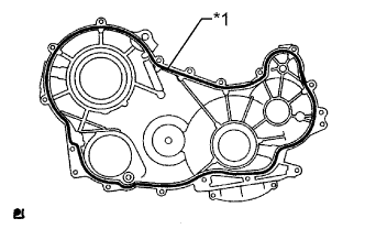
INSTALL TIMING GEAR CASE ASSEMBLY
-
Install 2 new O-rings to the cylinder block.
-
Remove any old seal packing (FIPG material) from the timing gear case and cylinder block.
-
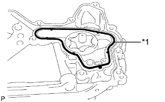
Text in Illustration *1 New Gasket Install a new gasket to the timing gear case.
-
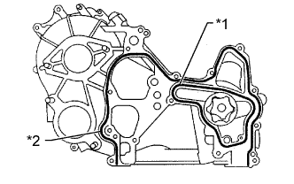
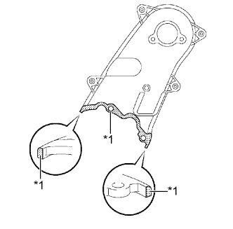
Text in Illustration *1 Gasket *2 Seal Packing Apply seal packing as shown in the illustration.
Seal packing Toyota Genuine Seal Packing Black, Three Bond 1207B or equivalent Seal diameter 4 mm (0.15 in.) Note
-
After applying seal packing, install the timing gear case within 3 minutes and tighten the bolts within 15 minutes.
-
Do not start the engine for at least 2 hours after the installation.
-
-
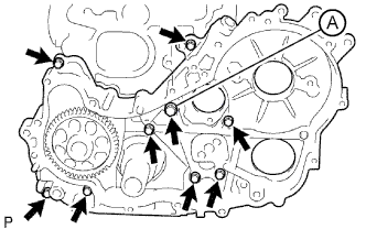
Install the timing gear case with union bolt A and the 8 bolts.
- Torque:
- 13 N*m { 133 kgf*cm, 10 ft.*lbf, for bolt }
- 16 N*m { 163 kgf*cm, 12 ft.*lbf, for union bolt A }
-
Make sure that the oil pump drive gear rotates smoothly.
If the gear does not rotate smoothly, loosen the 8 bolts and union bolt and turn the gear. Then tighten the 8 bolts and union bolt and check the gear again.
-
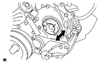
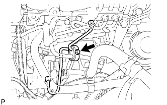
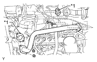
Install the No. 1 vacuum transmitting pipe with the nut.
- Torque:
- 8.0 N*m { 82 kgf*cm, 71 in.*lbf }
-
-
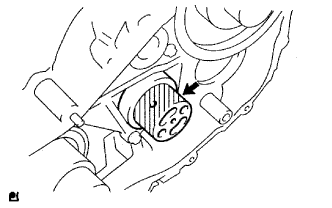
INSTALL OIL STRAINER SUB-ASSEMBLY
-
Install a new gasket and the oil strainer with the 2 bolts and nut.
- Torque:
- 8.0 N*m { 82 kgf*cm, 71 in.*lbf }
-
-
INSTALL OIL PAN SUB-ASSEMBLY
-
Remove any old seal packing (FIPG) from the oil pan and cylinder block.
-
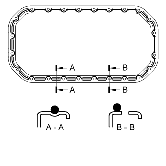
Apply seal packing as shown in the illustration.
Seal packing Toyota Genuine Seal Packing Black, Three Bond 1207B or equivalent Seal diameter 4 mm (0.15 in.) Note
-
After applying seal packing, install the oil pan within 3 minutes and tighten the bolts within 15 minutes.
-
Do not start the engine for at least 2 hours after the installation.
-
-
Install the oil pan with the 22 bolts and 2 nuts.
- Torque:
- 12 N*m { 122 kgf*cm, 9 ft.*lbf }
-
-
INSTALL ENGINE OIL LEVEL DIPSTICK GUIDE
-
Apply clean engine oil to a new O-ring.
-
Install the O-ring to the dipstick guide.
-
Install the dipstick guide with the bolt.
- Torque:
- 8.0 N*m { 82 kgf*cm, 71 in.*lbf }
-
-
INSTALL ENGINE OIL LEVEL DIPSTICK
-
INSTALL FUEL SUPPLY PUMP ASSEMBLY
-
Check that the injection gear in the timing gear case moves back and forth smoothly.
-
Install a new O-ring to the pump.
-
Apply a light coat of engine oil to the O-ring.
-
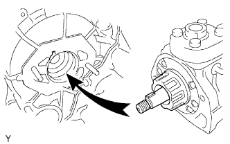
Align the set key on the drive shaft with the groove of the injection gear.
-
Install the pump with the 2 nuts.
- Torque:
- 21 N*m { 214 kgf*cm, 15 ft.*lbf }
-
Set a new O-ring before tightening the set nut.
-
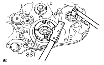
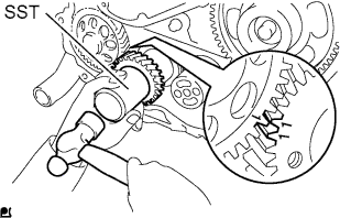
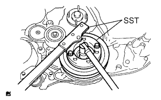
Using SST, hold the crankshaft pulley and install the set nut.
- SST
- 09213-58013
- 09330-00021
- Torque:
- 64 N*m { 653 kgf*cm, 47 ft.*lbf }
-
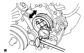
Move the pump drive shaft pulley back and forth to check the thrust clearance of the injection pump drive shaft.
Thrust clearance 0.15 to 0.55 mm (0.0059 to 0.0217 in.) If the clearance is not within the specified range, disassemble and reassemble the supply pump and pump drive shaft pulley. Then repeat step above.
-
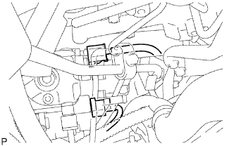
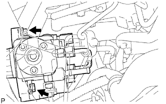
Connect the 2 connectors.
-
Connect the 2 fuel hoses.
-
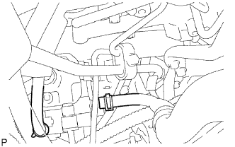
Temporarily install the fuel inlet pipe with the union nuts.
Note
-
If the supply pump is replaced, the fuel inlet pipe must be replaced.
-
Keep the fuel inlet pipe free of foreign matter.
-
-
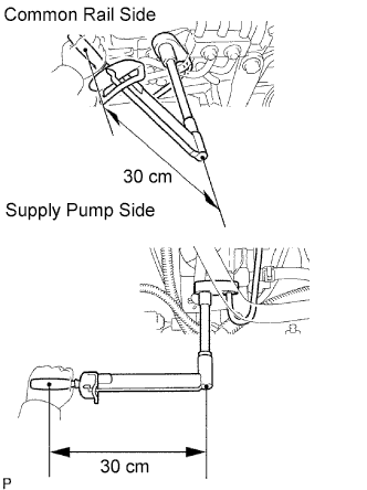
Using a 17 mm union nut wrench, tighten the injection pipe union nut on the common rail side.
- Torque:
- 32 N*m { 326 kgf*cm, 24 ft.*lbf, for use with union nut wrench }
- 35 N*m { 357 kgf*cm, 26 ft.*lbf, for use without union nut wrench }
Tech Tips
Use a torque wrench with a fulcrum length of 30 cm (11.81 in.).
-
Using a 17 mm union nut wrench, tighten the injection pipe union nut on the supply pump side.
- Torque:
- 32 N*m { 326 kgf*cm, 24 ft.*lbf, for use with union nut wrench }
- 35 N*m { 357 kgf*cm, 26 ft.*lbf, for use without union nut wrench }
Tech Tips
Use a torque wrench with a fulcrum length of 30 cm (11.81 in.).
-
Install the oil level gauge guide with the 2 bolts.
- Torque:
- 8.0 N*m { 82 kgf*cm, 71 in.*lbf }
-
Install the clamp with the bolt.
- Torque:
- 5.0 N*m { 51 kgf*cm, 44 in.*lbf }
-
-
INSTALL INJECTION GEAR
-
Install the injection gear and a new O-ring, and then temporarily install the nut. Using your hand, check the thrust clearance of the supply pump drive shaft by turning the injection gear.
Standard thrust clearance 0.15 to 0.55 mm (0.0059 to 0.0217 in.) Note
Fit the key (protrusion) of the supply pump to the key slot of the injection gear.
Tech Tips
If the clearance is not within the specified range, remove and reinstall the injection gear.
-
-
INSTALL CRANKSHAFT TIMING GEAR
-
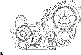
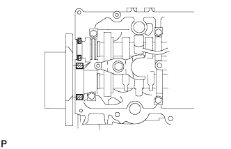
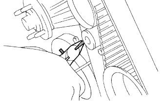
Align the "1" timing marks of the oil pump drive gear and crankshaft timing gear as shown in the illustration.
-
Using SST, install the crankshaft timing gear.
- SST
- 09223-00010
-
-
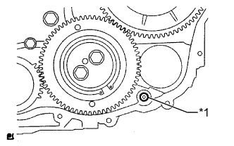
INSTALL NO. 1 IDLE GEAR
-
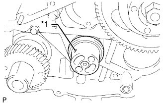
Text in Illustration *1 Oil Hole Install the No. 1 idle gear shaft to the cylinder block.
-
Apply a light coat engine oil to the No. 1 idle gear shaft shown in the illustration.
-
Text in Illustration *a Turn Align the "5" timing marks of the idle gear and crankshaft timing gear.
-
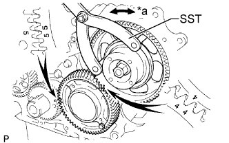
Using SST, turn the supply pump gear, and align the "4" timing marks of the idle gear and injection gear, and mesh the gears.
- SST
- 09960-10010 ( 09962-01000, 09963-00700 )
-
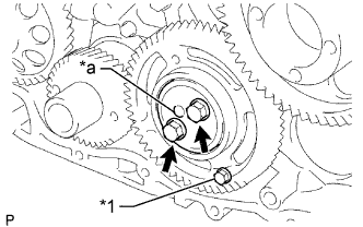
Text in Illustration *1 Service Bolt *a Protrusion Temporarily install the No. 1 idle gear and idle gear thrust plate with the 2 bolts.
Tech Tips
Face the thrust plate's protrusion outward.
-
Secure the No. 2 idle gear to the No. 1 idle gear with a service bolt.
- Torque:
- 8.0 N*m { 82 kgf*cm, 71 in.*lbf }
-
Tighten the 2 bolts.
- Torque:
- 50 N*m { 510 kgf*cm, 37 ft.*lbf }
-
Remove the service bolt.
-
Install the No. 1 crankshaft sensor plate.
-
-
INSTALL TIMING GEAR COVER
-
Text in Illustration *1 New O-Ring Install a new O-ring to the timing gear case.
-
Remove any old seal packing (FIPG material) from the timing gear cover.
-
Text in Illustration *1 Seal Packing Apply seal packing as shown in the illustration.
Seal packing Toyota Genuine Seal Packing Black, Three Bond 1207B or equivalent Seal diameter 4 mm (0.15 in.) Note
-
After applying seal packing, install the gear cover within 3 minutes and tighten the bolts and nuts within 15 minutes.
-
Do not start the engine for at least 2 hours after the installation.
-
-
Install the cover with the 14 bolts and 2 nuts.
- Torque:
- 13 N*m { 133 kgf*cm, 10 ft.*lbf }
-
Install the wire harness clamp.
-
-
INSTALL CRANKSHAFT POSITION SENSOR
-
Install the crankshaft position sensor with the bolt.
- Torque:
- 8.5 N*m { 87 kgf*cm, 75 in.*lbf }
-
-
INSTALL CAMSHAFT POSITION SENSOR
-
Install the camshaft position sensor with the bolt.
- Torque:
- 8.5 N*m { 87 kgf*cm, 75 in.*lbf }
-
-
INSTALL CRANKSHAFT PULLEY
-
Align the pulley set key with the key groove of the pulley.
-
Using SST, install the pulley bolt.
- SST
- 09213-58014
- 09330-00021
- Torque:
- 365 N*m { 3722 kgf*cm, 269 ft.*lbf }
-
-
INSTALL PUMP DRIVE SHAFT PULLEY
-
Install a new O-ring to the supply pump.
-
Temporarily install the supply pump with the nut.
-
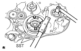
Using SST, hold the crankshaft pulley and tighten the nut.
- SST
- 09213-58014
- 09330-00021
- Torque:
- 64 N*m { 650 kgf*cm, 47 ft.*lbf }
-
Install the No. 2 camshaft timing pulley flange and pump drive shaft pulley with the 4 bolts.
- Torque:
- 31 N*m { 316 kgf*cm, 23 ft.*lbf }
-

Using a dial indicator, check the thrust clearance of the pump drive shaft while moving the pump drive shaft pulley back and forth.
Standard thrust clearance 0.15 to 0.55 mm (0.0059 to 0.0217 in.) If the clearance is not within the specified range, disassemble and reassemble the supply pump and pump drive shaft pulley. Then repeat the step above.
-
-
INSTALL VANE PUMP ASSEMBLY
-
Install a new O-ring to the vane pump.
-
Install the vane pump with the 2 nuts.
- Torque:
- 41 N*m { 418 kgf*cm, 30 ft.*lbf }
-
-
INSTALL VACUUM PUMP ASSEMBLY
-
Install 2 new O-rings to the vacuum pump.
-
Install the vacuum pump with the 2 nuts.
- Torque:
- 21 N*m { 210 kgf*cm, 15 ft.*lbf }
-
-
INSTALL ENGINE WATER PUMP ASSEMBLY
-
Install a new gasket and the water pump with the 5 bolts and 2 nuts.
- Torque:
- 13 N*m { 133 kgf*cm, 10 ft.*lbf }
-
-
INSTALL NO. 2 TIMING BELT COVER
-
Text in Illustration *1 Seal Packing Apply seal packing (FIPG) to the specified areas shown in the illustration.
Seal packing Toyota Genuine Seal Packing Black, Three Bond 1207B or equivalent Note
After applying seal packing, install the No. 2 timing belt cover within 3 minutes and tighten the bolts and nut within 15 minutes.
-
Clean the bolts and their holes.
-
Apply adhesive to 2 or 3 threads at the end of each of the 4 bolts.
Adhesive Toyota Genuine Adhesive 1324, Three Bond 1324 or equivalent -
Install the No. 2 timing belt cover with the 4 bolts and nut.
- Torque:
- 10 N*m { 102 kgf*cm, 7 ft.*lbf }
-
-
INSTALL NO. 1 TIMING BELT IDLER SUB-ASSEMBLY
-
Install the timing belt idler and a new spacer with the bolt.
- Torque:
- 35 N*m { 357 kgf*cm, 26 ft.*lbf }
-
-
INSTALL CAMSHAFT TIMING PULLEY
-
Install the camshaft timing pulley.
-
Install the bolt of the camshaft timing pulley while holding the camshaft with a wrench.
- Torque:
- 98 N*m { 1000 kgf*cm, 72 ft.*lbf }
-
-
INSTALL CYLINDER HEAD COVER SUB-ASSEMBLY
-
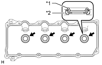
Text in Illustration *1 No. 3 Cylinder Head Cover Gasket *2 Cylinder Head Cover Install 4 new No. 3 cylinder head cover gaskets to the cylinder head cover in the directions shown in the illustration.
Note
-
Do not install the No. 3 cylinder head cover gaskets at an angle.
-
Check that there is no foreign matter at the installation location of the No. 3 cylinder head cover gaskets.
-
-
Remove any old seal packing (FIPG material) from the cylinder head.
-
Apply seal packing to the specific areas shown in the illustration.
Seal packing Toyota Genuine Seal Packing Black, Three Bond 1207B or equivalent Text in Illustration 
Seal Packing Note
-
Remove any oil from the contact surface.
-
Install the head cover within 3 minutes after applying seal packing.
-
Do not start the engine for at least 2 hours after installing the seal packing.
-
-
Install a new cylinder head cover gasket and the cylinder head cover with the 10 bolts and 2 nuts.
- Torque:
- 9.0 N*m { 92 kgf*cm, 80 in.*lbf }
-
Connect the ventilation hose.
-
Install 4 new nozzle holder seals.
-
Connect the 4 injector connectors and install the 3 bolts.
- Torque:
- 13 N*m { 127 kgf*cm, 9 ft.*lbf }
-
-
INSTALL NO. 2 NOZZLE LEAKAGE PIPE ASSEMBLY
-
w/ Intercooler:
-
Temporarily install the No. 2 nozzle leakage pipe with the 3 bolts.
-
Temporarily install a new gasket and the union bolt.
-
Tighten the 3 bolts and union bolt.
- Torque:
- for bolt
- 13 N*m { 130 kgf*cm, 9 ft.*lbf }
- for union bolt
- 21 N*m { 214 kgf*cm, 15 ft.*lbf }
-
-
w/o Intercooler:
-
Temporarily install the No. 2 nozzle leakage pipe with the 2 bolts.
-
Temporarily install a new gasket and the union bolt.
-
Tighten the 2 bolts and union bolt.
- Torque:
- for bolt
- 13 N*m { 130 kgf*cm, 9 ft.*lbf }
- for union bolt
- 21 N*m { 214 kgf*cm, 15 ft.*lbf }
-
-
Connect the 3 fuel hoses.
-
-
INSTALL NO. 4 INJECTION PIPE SUB-ASSEMBLY
Note
-
When replacing an injector, it is necessary to replace the 4 injection pipes with new ones.
-
Keep the joints of the injection pipe clean.
-
Temporarily install the No. 4 injection pipe with the union nuts.
-
w/ Intercooler:
Install the bolt.
- Torque:
- 5.0 N*m { 51 kgf*cm, 44 in.*lbf }
Note
-
If an injection pipe clamp is removed from the No. 4 injection pipe, replace the injection pipe clamp with a new one.
-
Make sure that the inner rubbers of the injection pipe fit inside the clamps.
-
When installing the pipe, check that the inner rubbers and the clamps are in their proper positions.
-
w/o Intercooler:
Install the 2 bolts.
- Torque:
- 13 N*m { 130 kgf*cm, 9 ft.*lbf }
Note
-
If an injection pipe clamp is removed from the No. 4 injection pipe, replace the injection pipe clamp with a new one.
-
Make sure that the inner rubbers of the injection pipe fit inside the clamps.
-
When installing the pipe, check that the inner rubbers and the clamps are in their proper positions.
-
Using a 17 mm union nut wrench, tighten the injection pipe union nut on the common rail side.
- Torque:
- 35 N*m { 357 kgf*cm, 26 ft.*lbf }
Note
Use the formula to calculate special torque values for situations where a union nut wrench is combined with a torque wrench Click here.
-
Using a 17 mm union nut wrench, tighten the injection pipe union nuts on the injector side.
- Torque:
- 35 N*m { 357 kgf*cm, 26 ft.*lbf }
Note
Use the formula to calculate special torque values for situations where a union nut wrench is combined with a torque wrench Click here.
-
-
TEMPORARILY TIGHTEN ELECTRIC EGR CONTROL VALVE ASSEMBLY (w/ Intercooler)
-
Place a new gasket, the electric EGR control valve, another new gasket and the intake air connector onto the stud bolts of the No. 2 intake air connector and temporarily install the 3 nuts labeled A in the illustration.
Note
Temporarily install the nuts so that 0 to 2 threads of each stud bolt are visible as shown in the illustration.
-
Install a new gasket and the EGR valve adapter to the electric EGR control valve with the 2 bolts labeled B in the illustration.
- Torque:
- 13 N*m { 133 kgf*cm, 10 ft.*lbf }
Note
Make sure the claws of the gasket face the electric EGR control valve as shown in the illustration.
-
Set a new gasket on the intake manifold.
Note
Make sure the claws of the gasket face the intake manifold as shown in the illustration.
-
Temporarily install the intake air connector to the intake manifold with the 3 bolts labeled C in the illustration.
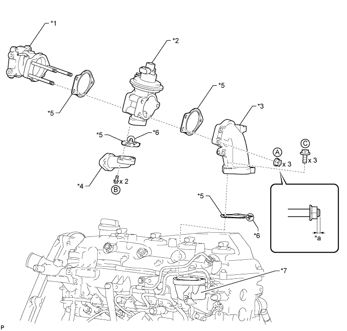
Text in Illustration *1 No. 2 Intake Air Connector *2 Electric EGR Control Valve *3 Intake Air Connector *4 EGR Valve Adapter *5 New Gasket *6 Claw *7 Intake Manifold - - *a 0 to 2 threads - -
-
-
TIGHTEN NO. 1 EGR PIPE SUB-ASSEMBLY (w/ Intercooler)
-
w/ Intercooler:
-
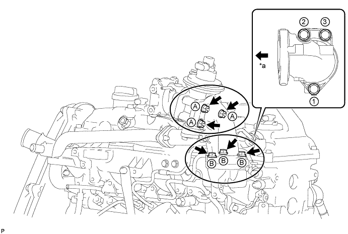
Temporarily install the No. 1 EGR pipe and 2 new gaskets to the cylinder head and EGR valve adapter with the 2 nuts and 2 bolts.
Note
Make sure the claws of the gasket face the No. 1 EGR pipe as shown in the illustration.
-
Tighten the 2 nuts labeled A.
- Torque:
- 13 N*m { 133 kgf*cm, 10 ft.*lbf }
-
Tighten the 2 bolts labeled B.
- Torque:
- 13 N*m { 133 kgf*cm, 10 ft.*lbf }
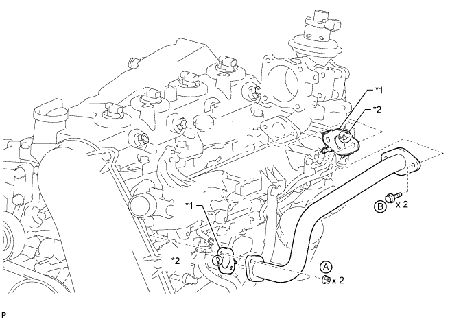
Text in Illustration *1 New Gasket *2 Claw
-
-
Text in Illustration *1 Claw w/o Intercooler:
Install 2 new gaskets and the No. 1 EGR pipe with the 2 nuts and 2 bolts.
- Torque:
- 13 N*m { 133 kgf*cm, 10 ft.*lbf }
Tech Tips
Make sure the claws of the gasket face the No. 1 EGR pipe.
-
-
TIGHTEN INTAKE AIR CONNECTOR (w/ Intercooler)
-
Tighten the 3 nuts labeled A in the illustration.
- Torque:
- 20 N*m { 204 kgf*cm, 15 ft.*lbf }
-
Tighten the 3 bolts labeled B in the illustration.
- Torque:
- 20 N*m { 204 kgf*cm, 15 ft.*lbf }
Note
Tighten the bolts in the order shown in the illustration.
Text in Illustration *a Front Side of Vehicle - -
-
-
INSTALL NO. 2 INTAKE AIR CONNECTOR BRACKET (w/ Intercooler)
-
w/ Intercooler:
-
Temporarily install the No. 2 intake air connector bracket with the 3 bolts.
-
Tighten the bolt labeled A.
- Torque:
- 20 N*m { 204 kgf*cm, 15 ft.*lbf }
-
Tighten the 2 bolts labeled B.
- Torque:
- 20 N*m { 204 kgf*cm, 15 ft.*lbf }
-
-
w/o Intercooler:
Install the No. 2 intake air connector bracket with the 3 bolts.
- Torque:
- 20 N*m { 204 kgf*cm, 15 ft.*lbf }
-
-
INSTALL ELECTRIC VACUUM REGULATING VALVE ASSEMBLY (w/ Intercooler)
-
w/ Intercooler:
-
Install the electric vacuum regulating valve bracket with the 2 bolts.
- Torque:
- 20 N*m { 204 kgf*cm, 15 ft.*lbf }
-
Install the No. 1 gas filter with gas filter bracket with the bolt.
- Torque:
- 20 N*m { 204 kgf*cm, 15 ft.*lbf }
-
Connect the 6 vacuum hoses.
Note
Be sure to securely connect the vacuum hoses.
-
Connect the 2 connectors.
-
-
w/o Intercooler:
-
Install the electric vacuum regulating valve together with the bracket with the 2 bolts.
- Torque:
- 20 N*m { 204 kgf*cm, 15 ft.*lbf }
-
Connect the 2 vacuum hoses.
-
Connect the connector.
-
-
-
CONNECT NO. 3 WATER BY-PASS PIPE (w/ Intercooler)
-
Connect the No. 3 water by-pass pipe with wire harness with the 2 bolts.
- Torque:
- 18 N*m { 184 kgf*cm, 13 ft.*lbf }
-
-
INSTALL NO. 1, NO. 2 AND NO. 3 INJECTION PIPE SUB-ASSEMBLY
Note
-
When replacing an injector, it is necessary to replace the 4 injection pipes with new ones.
-
Keep the joints of the injection pipes clean.
-
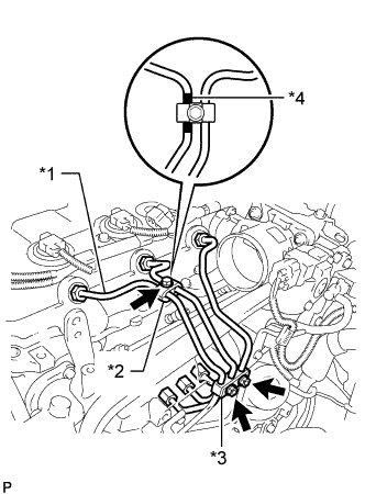
Temporarily install the No. 1, No. 2 and No. 3 injection pipes with the union nuts.
-
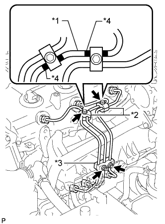
Text in Illustration *1 No. 2 Injection Pipe *2 No. 2 Injection Pipe Clamp *3 No. 3 Injection Pipe Clamp *4 Painted Mark w/ Intercooler:
Install the No. 2 and No. 3 injection pipe clamps with the 2 bolts and 2 nuts as shown in the illustration.
- Torque:
- 5.0 N*m { 51 kgf*cm, 44 in.*lbf }
Tech Tips
If the painted mark on the No. 2 injection pipe has disappeared, use the illustration as a reference to install the clamps.
-
Text in Illustration *1 No. 1 Injection Pipe *2 No. 2 Injection Pipe Clamp *3 No. 3 Injection Pipe Clamp *4 Painted Mark w/o Intercooler:
Install the No. 2 and No. 3 injection pipe clamps with the bolt and 2 nuts as shown in the illustration.
- Torque:
- 5.0 N*m { 51 kgf*cm, 44 in.*lbf }
Tech Tips
If the painted mark on the No. 1 injection pipe has disappeared, use the illustration as a reference to install the clamps.
-
Using a 17 mm union nut wrench, tighten the injection pipe union nuts on the common rail side.
- Torque:
- 35 N*m { 357 kgf*cm, 26 ft.*lbf }
Note
Use the formula to calculate special torque values for situations where a union nut wrench is combined with a torque wrench Click here.
-
Using a 17 mm union nut wrench, tighten the injection pipe union nuts on the injector side.
- Torque:
- 35 N*m { 357 kgf*cm, 26 ft.*lbf }
Note
Use the formula to calculate special torque values for situations where a union nut wrench is combined with a torque wrench Click here.
-
-
REMOVE DIESEL THROTTLE BODY ASSEMBLY (w/ Intercooler)
-
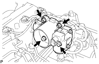
Install a new gasket and the throttle body with the 2 bolts and 2 nuts.
- Torque:
- 20 N*m { 204 kgf*cm, 15 ft.*lbf }
-
Connect the 2 connectors.
-
-
INSTALL FUEL INLET PIPE SUB-ASSEMBLY
-
Temporarily install the fuel inlet pipe with the union nuts.
Note
-
When replacing the fuel supply pump, it is necessary to replace the fuel inlet pipe with a new one.
-
Keep the fuel inlet pipe free of foreign matter.
-
-
Using a 17 mm union nut wrench, tighten the fuel inlet pipe union nut on the common rail side.
- Torque:
- 35 N*m { 357 kgf*cm, 26 ft.*lbf }
Note
Use the formula to calculate special torque values for situations where a union nut wrench is combined with a torque wrench Click here.
-
Using a 17 mm union nut wrench, tighten the fuel inlet pipe union nut on the fuel supply pump side.
- Torque:
- 35 N*m { 357 kgf*cm, 26 ft.*lbf }
Note
Use the formula to calculate special torque values for situations where a union nut wrench is combined with a torque wrench Click here.
-
-
INSTALL MANIFOLD STAY (w/o Intercooler)
-
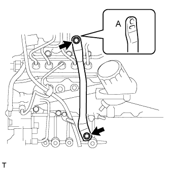
Install the manifold stay with the 2 bolts.
- Torque:
- 19 N*m { 194 kgf*cm, 14 ft.*lbf }
Tech Tips
The manifold stay indented area (labeled A) must face the manifold.
-
-
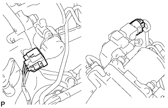
INSTALL MANIFOLD STAY WITH VACUUM SWITCHING VALVE (w/ Intercooler)
-
Install the manifold stay with vacuum switching valve with the 2 bolts.
- Torque:
- 19 N*m { 194 kgf*cm, 14 ft.*lbf }
-
Connect the 3 vacuum transmitting hoses and 2 vacuum switching valve connectors.
Note
Be sure to securely connect the vacuum transmitting hose.
-
-
INSTALL V-RIBBED BELT TENSIONER ASSEMBLY
-
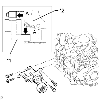
Text in Illustration *1 V-ribbed Belt Tensioner *2 Cylinder Block Install the V-ribbed belt tensioner with the 4 bolts.
- Torque:
- 21 N*m { 214 kgf*cm, 15 ft.*lbf }
Tech Tips
Firmly press and hold the tensioner against the cylinder block to eliminate any gaps in the areas labeled A in the illustration. Then uniformly tighten the 4 bolts.
-
-
INSTALL NO. 1 COMPRESSOR MOUNTING BRACKET
-
Install the No. 1 compressor mounting bracket with the 4 bolts.
- Torque:
- 45 N*m { 459 kgf*cm, 33 ft.*lbf }
-
-
INSTALL GENERATOR BRACKET
-
Install the generator bracket with the bolt.
- Torque:
- 25 N*m { 255 kgf*cm, 18 ft.*lbf }
-
-
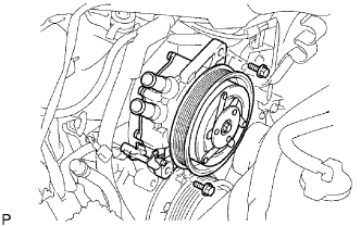
INSTALL GENERATOR ASSEMBLY
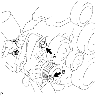
-
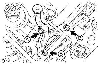
Install the generator with the 2 bolts.
- Torque:
- 62 N*m { 632 kgf*cm, 46 ft.*lbf, for bolt A }
- 25 N*m { 255 kgf*cm, 18 ft.*lbf, for bolt B }
-
Install the generator wire with the nut.
- Torque:
- 9.8 N*m { 100 kgf*cm, 87 in.*lbf }
-
Connect the generator connector.
-
-
INSTALL NO. 2 IDLE PULLEY ASSEMBLY
-
INSTALL NO. 1 VISCOUS HEATER BRACKET SUB-ASSEMBLY
-
Install the No. 1 viscous heater bracket with the 2 bolts.
- Torque:
- 45 N*m { 459 kgf*cm, 33 ft.*lbf }
-
-
INSTALL VISCOUS WITH MAGNET CLUTCH HEATER ASSEMBLY
-
Install the viscous with magnet clutch heater with the 2 bolt.
- Torque:
- 45 N*m { 459 kgf*cm, 33 ft.*lbf }
-
Connect the connect.
-
-
INSTALL TIMING BELT
-
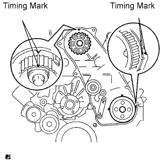
Check that the timing marks are aligned as shown in the illustration.
Tech Tips
If reusing the timing belt, align the points marked during removal, and install the belt with the arrow pointing in the direction of engine revolution.
Note
-
The engine should be cold.
-
When turning the crankshaft, the valve heads will hit against the piston's top position. Do not turn it more than necessary.
-
-
Using a 10 mm hexagon wrench, install the timing belt idler pulley and new washer with the bolt.
- Torque:
- 35 N*m { 357 kgf*cm, 26 ft.*lbf }
-
Check that the idler pulley moves smoothly.
If it does not move smoothly, check the idler sub-assembly and washer.
-
Install the timing belt to the pump drive shaft pulley, camshaft timing pulley and No. 1 timing belt idler in sequence.
-
Place the tensioner upright. Then set the press to the top of the tensioner.
Note
-
Do not scratch or deform the rod end.
-
Press in the tensioner rod upward.
-
Protect the tip of the push rod with a cloth in order to prevent damage.
-
-
Using a press, slowly push in the push rod using 981 to 9800 N (100 to 999 kgf, 220 to 2203 lbf) of force.
Note
Do not impose a load of over 9800 N (100 to 999 kgf, 2203 lbf) to the push rod.
-
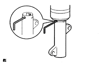
Align the holes of the push rod and housing. Then pass a 1.27 mm hexagon wrench through the holes to keep the setting position of the push rod.
-
Install the timing belt tensioner with the 2 bolts while pushing the idler pulley toward the timing belt.
-
Tighten the 2 bolts.
- Torque:
- 13 N*m { 133 kgf*cm, 10 ft.*lbf }
Note
Uniformly tighten the 2 bolts and install the tensioner.
-
Remove the 1.5 mm hexagon wrench from the tensioner.
-
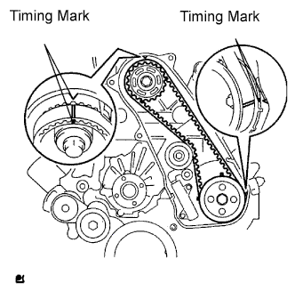
Turn the crankshaft clockwise 720° and check that the timing marks are aligned as shown in the illustration.
-
-
INSTALL NO. 1 TIMING BELT COVER
-
Install the timing belt cover with the 6 bolts.
- Torque:
- 6.0 N*m { 61 kgf*cm, 53 in.*lbf }
-
Install the wire harness clamp.
-
Install the water hose clamp with the bolt.
- Torque:
- 18 N*m { 184 kgf*cm, 13 ft.*lbf }
-
-
INSTALL ENGINE ASSEMBLY