CAN COMMUNICATION SYSTEM Tire Pressure Monitor ECU Communication Stop Mode
DESCRIPTION
| Detection Item | Symptom | Trouble Area |
|---|---|---|
| Tire Pressure Monitor ECU Communication Stop Mode | Either condition is met:
|
|
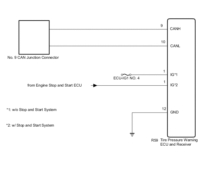
WIRING DIAGRAM
Figure 1. for Tire PressureWarning ECU and Receiver Integrated with Electrical Key Receiver:
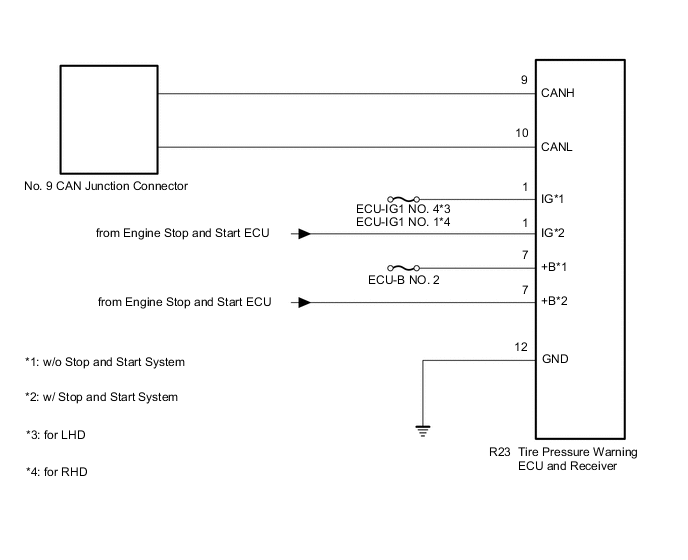
Figure 2. for Tire PressureWarning ECU and Receiver (Stand Alone) (Roof):
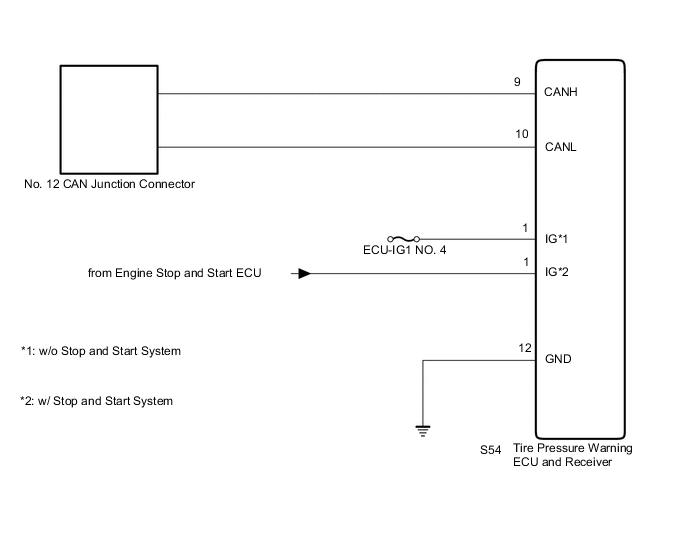
Figure 3. for Tire PressureWarning ECU and Receiver (Stand Alone) (Quarter Panel):
CAUTION / NOTICE / HINT
Note
-
Before measuring the resistance of the CAN bus, turn the engine switch off and leave the vehicle for 1 minute or more without operating the key or any switches, or opening or closing the doors. After that, disconnect the cable from the negative (-) battery terminal and leave the vehicle for 1 minute or more before measuring the resistance.
-
After turning the engine switch off, waiting time may be required before disconnecting the cable from the negative (-) battery terminal. Therefore, make sure to read the disconnecting the cable from the negative (-) battery terminal notices before proceeding with work.
-
Because the order of diagnosis is important to allow correct diagnosis, make sure to begin troubleshooting using How to Proceed with Troubleshooting when CAN communication system related DTCs are output.
-
After performing repairs, perform the DTC check procedure and confirm that the DTCs are not output again.
-
DTC check procedure: Turn the engine switch on (IG) and wait for at least 63 seconds.
-
After the repair, perform the CAN bus check and check that all the ECUs and sensors connected to the CAN communication system are displayed.
-
Inspect the fuses for circuits related to this system before performing the following procedure.
Tech Tips
-
Operating the engine switch, any other switches or a door triggers related ECU and sensor communication on the CAN. This communication will cause the resistance value to change.
-
Even after DTCs are cleared, if a DTC is stored again after driving the vehicle for a while, the malfunction may be occurring due to vibration of the vehicle. In such a case, wiggling the ECUs or wire harness while performing the inspection below may help determine the cause of the malfunction.
PROCEDURE
-
CHECK VEHICLE TYPE
-
Check vehicle type.
Result Result Proceed to for Tire Pressure Warning ECU and Receiver Integrated with Electrical Key Receiver A for Tire Pressure Warning ECU and Receiver (Stand Alone) (Roof) B for Tire Pressure Warning ECU and Receiver (Stand Alone) (Quarter Panel) C
B 
CHECK FOR OPEN IN CAN BUS LINES (TIRE PRESSURE WARNING ECU AND RECEIVER BRANCH LINE) Click here
C
CHECK FOR OPEN IN CAN BUS LINES (TIRE PRESSURE WARNING ECU AND RECEIVER BRANCH LINE) Click here
A 
-
-
CHECK FOR OPEN IN CAN BUS LINES (TIRE PRESSURE WARNING ECU AND RECEIVER BRANCH LINE)
-
Disconnect the cable from the negative (-) battery terminal.
-
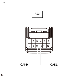
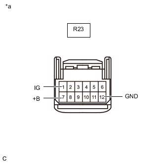
*a Front view of wire harness connector
(to Tire Pressure Warning ECU and Receiver)
Disconnect the R23 tire pressure warning ECU and receiver connector.
-
Measure the resistance according to the value(s) in the table below.
Standard Resistance Tester Connection Condition Specified Condition R23-9 (CANH) - R23-10 (CANL) Cable disconnected from negative (-) battery terminal 54 to 69 Ω Result Result Proceed to OK (w/o Stop and Start System) A OK (w/ Stop and Start System) B NG C
B
CHECK HARNESS AND CONNECTOR (POWER SOURCE CIRCUIT) Click here
C 
REPAIR OR REPLACE CAN BRANCH LINES OR CONNECTOR (TIRE PRESSURE WARNING ECU AND RECEIVER)
A
-
-
CHECK HARNESS AND CONNECTOR (POWER SOURCE CIRCUIT)
-
*a Front view of wire harness connector
(to Tire Pressure Warning ECU and Receiver)
Measure the resistance according to the value(s) in the table below.
Standard Resistance Tester Connection Condition Specified Condition R23-12 (GND) - Body ground Cable disconnected from negative (-) battery terminal Below 1 Ω -
Reconnect the cable to the negative (-) battery terminal.
-
Measure the voltage according to the value(s) in the table below.
Standard Voltage Tester Connection Condition Specified Condition R23-1 (IG) - Body ground Engine switch on (IG) 11 to 14 V R23-7 (+B) - Body ground Always 11 to 14 V Result Result OK NG
OK
REPLACE TIRE PRESSURE WARNING ECU AND RECEIVER Click here
NG
REPAIR OR REPLACE HARNESS OR CONNECTOR (POWER SOURCE CIRCUIT)
-
-
CHECK HARNESS AND CONNECTOR (POWER SOURCE CIRCUIT)
-
*a Front view of wire harness connector
(to Tire Pressure Warning ECU and Receiver)
Measure the resistance according to the value(s) in the table below.
Standard Resistance Tester Connection Condition Specified Condition R23-12 (GND) - Body ground Cable disconnected from negative (-) battery terminal Below 1 Ω -
Reconnect the cable to the negative (-) battery terminal.
-
Measure the voltage according to the value(s) in the table below.
Standard Voltage Tester Connection Condition Specified Condition R23-1 (IG) - Body ground Engine switch on (IG) 11 to 14 V R23-7 (+B) - Body ground Always 11 to 14 V Result Result Proceed to OK A NG (except GND terminal) B NG (GND terminal) C
A
REPLACE TIRE PRESSURE WARNING ECU AND RECEIVER Click here
B
GO TO STOP AND START SYSTEM (FOR BACKUP BOOST CONVERTER CIRCUIT) Click here
C
REPAIR OR REPLACE HARNESS OR CONNECTOR (POWER SOURCE CIRCUIT)
-
-
CHECK FOR OPEN IN CAN BUS LINES (TIRE PRESSURE WARNING ECU AND RECEIVER BRANCH LINE)
-
Disconnect the cable from the negative (-) battery terminal.
-

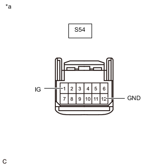
*a Front view of wire harness connector
(to Tire Pressure Warning ECU and Receiver)
Disconnect the S54 tire pressure warning ECU and receiver connector.
-
Measure the resistance according to the value(s) in the table below.
Standard Resistance Tester Connection Condition Specified Condition S54-9 (CANH) - S54-10 (CANL) Cable disconnected from negative (-) battery terminal 54 to 69 Ω Result Result Proceed to OK (w/o Stop and Start System) A OK (w/ Stop and Start System) B NG C
B
CHECK HARNESS AND CONNECTOR (POWER SOURCE CIRCUIT) Click here
C
REPAIR OR REPLACE CAN BRANCH LINES OR CONNECTOR (TIRE PRESSURE WARNING ECU AND RECEIVER)
A
-
-
CHECK HARNESS AND CONNECTOR (POWER SOURCE CIRCUIT)
-
*a Front view of wire harness connector
(to Tire Pressure Warning ECU and Receiver)
Measure the resistance according to the value(s) in the table below.
Standard Resistance Tester Connection Condition Specified Condition S54-12 (GND) - Body ground Cable disconnected from negative (-) battery terminal Below 1 Ω -
Reconnect the cable to the negative (-) battery terminal.
-
Measure the voltage according to the value(s) in the table below.
Standard Voltage Tester Connection Condition Specified Condition S54-1 (IG) - Body ground Engine switch on (IG) 11 to 14 V Result Result OK NG
OK
REPLACE TIRE PRESSURE WARNING ECU AND RECEIVER Click here
NG
REPAIR OR REPLACE HARNESS OR CONNECTOR (POWER SOURCE CIRCUIT)
-
-
CHECK HARNESS AND CONNECTOR (POWER SOURCE CIRCUIT)
-

*a Front view of wire harness connector
(to Tire Pressure Warning ECU and Receiver)
Measure the resistance according to the value(s) in the table below.
Standard Resistance Tester Connection Condition Specified Condition S54-12 (GND) - Body ground Cable disconnected from negative (-) battery terminal Below 1 Ω -
Reconnect the cable to the negative (-) battery terminal.
-
Measure the voltage according to the value(s) in the table below.
Standard Voltage Tester Connection Condition Specified Condition S54-1 (IG) - Body ground Engine switch on (IG) 11 to 14 V Result Result Proceed to OK A NG (except GND terminal) B NG (GND terminal) C
A
REPLACE TIRE PRESSURE WARNING ECU AND RECEIVER Click here
B
GO TO STOP AND START SYSTEM (FOR BACKUP BOOST CONVERTER CIRCUIT) Click here
C
REPAIR OR REPLACE HARNESS OR CONNECTOR (POWER SOURCE CIRCUIT)
-
-
CHECK FOR OPEN IN CAN BUS LINES (TIRE PRESSURE WARNING ECU AND RECEIVER BRANCH LINE)
-
Disconnect the cable from the negative (-) battery terminal.
-

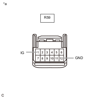
*a Front view of wire harness connector
(to Tire Pressure Warning ECU and Receiver)
Disconnect the R59 tire pressure warning ECU and receiver connector.
-
Measure the resistance according to the value(s) in the table below.
Standard Resistance Tester Connection Condition Specified Condition R59-9 (CANH) - R59-10 (CANL) Cable disconnected from negative (-) battery terminal 54 to 69 Ω Result Result Proceed to OK (w/o Stop and Start System) A OK (w/ Stop and Start System) B NG C
B
CHECK HARNESS AND CONNECTOR (POWER SOURCE CIRCUIT) Click here
C
REPAIR OR REPLACE CAN BRANCH LINES OR CONNECTOR (TIRE PRESSURE WARNING ECU AND RECEIVER)
A
-
-
CHECK HARNESS AND CONNECTOR (POWER SOURCE CIRCUIT)
-
*a Front view of wire harness connector
(to Tire Pressure Warning ECU and Receiver)
Measure the resistance according to the value(s) in the table below.
Standard Resistance Tester Connection Condition Specified Condition R59-12 (GND) - Body ground Cable disconnected from negative (-) battery terminal Below 1 Ω -
Reconnect the cable to the negative (-) battery terminal.
-
Measure the voltage according to the value(s) in the table below.
Standard Voltage Tester Connection Condition Specified Condition R59-1 (IG) - Body ground Engine switch on (IG) 11 to 14 V Result Result OK NG
OK
REPLACE TIRE PRESSURE WARNING ECU AND RECEIVER Click here
NG
REPAIR OR REPLACE HARNESS OR CONNECTOR (POWER SOURCE CIRCUIT)
-
-
CHECK HARNESS AND CONNECTOR (POWER SOURCE CIRCUIT)
-
*a Front view of wire harness connector
(to Tire Pressure Warning ECU and Receiver)
Measure the resistance according to the value(s) in the table below.
Standard Resistance Tester Connection Condition Specified Condition R59-12 (GND) - Body ground Cable disconnected from negative (-) battery terminal Below 1 Ω -
Reconnect the cable to the negative (-) battery terminal.
-
Measure the voltage according to the value(s) in the table below.
Standard Voltage Tester Connection Condition Specified Condition R59-1 (IG) - Body ground Engine switch on (IG) 11 to 14 V Result Result Proceed to OK A NG (except GND terminal) B NG (GND terminal) C
A
REPLACE TIRE PRESSURE WARNING ECU AND RECEIVER Click here
B
GO TO STOP AND START SYSTEM (FOR BACKUP BOOST CONVERTER CIRCUIT) Click here
C
REPAIR OR REPLACE HARNESS OR CONNECTOR (POWER SOURCE CIRCUIT)
-