COMPRESSOR(for 8AR-FTS) REMOVAL
CAUTION / NOTICE / HINT
The necessary procedures (adjustment, calibration, initialization or registration) that must be performed after parts are removed and installed, or replaced during compressor removal/installation are shown below.
| Replaced Part or Performed Procedure | Necessary Procedure | Effect/Inoperative Function when Necessary Procedure not Performed | Link |
|---|---|---|---|
| Disconnect cable from negative (-) battery terminal | Memorize steering angle neutral point | LKA /LDA system | |
| Intelligent clearance sonar system*1 | |||
| Pre-crash Safety System | |||
| Lighting system (EXT)
|
|||
| Adaptive high beam system | |||
| Drive the vehicle until stop and start control is permitted (approximately 15 to 60 minutes) | Stop and start system | ||
| Memorize steering angle neutral point | Parking Assist Monitor System (w/ Parallel Parking Assist Function) | ||
| Parking Assist Monitor System (w/o Parallel Parking Assist Function) | |||
| Panoramic view monitor system | |||
| Initialize back door lock | Power door lock control system | ||
| Reset back door close position | Power back door system | ||
| Replacement of battery |
|
Stop and start system | |
|
Front television camera view adjustment | Panoramic view monitor system | Click here for Initialization Click here for Calibration |
| Front bumper assembly (w/ Intelligent clearance sonar system) |
|
|
Click here Click here
PROCEDURE
-
RECOVER REFRIGERANT FROM REFRIGERATION SYSTEM
for HFC-134a (R134a):
for HFO-1234yf (R1234yf):
-
REMOVE V-RIBBED BELT
-
REMOVE RADIATOR ASSEMBLY
-
DISCONNECT SUCTION HOSE SUB-ASSEMBLY
-
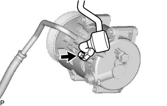
Remove the bolt and disconnect the suction hose sub-assembly from the compressor assembly with pulley.
-
Remove the O-ring from the suction hose sub-assembly.
Note
Seal the openings of the disconnected parts using vinyl tape to prevent moisture and foreign matter from entering them.
-
-
DISCONNECT DISCHARGE HOSE SUB-ASSEMBLY
-
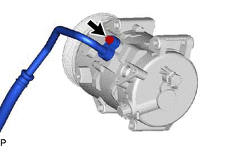
Remove the bolt and disconnect the discharge hose sub-assembly from the compressor assembly with pulley.
-
Remove the O-ring from the discharge hose sub-assembly.
Note
Seal the openings of the disconnected parts using vinyl tape to prevent moisture and foreign matter from entering them.
-
-
REMOVE COMPRESSOR ASSEMBLY WITH PULLEY
-
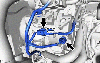
Disconnect each connector.
-
Disengage the clamp.
-
for Type A:
-
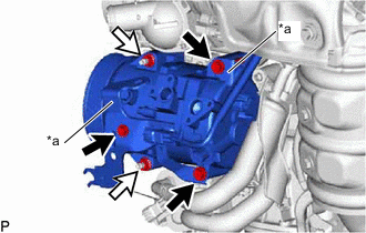
*a Bracket 
Bolt 
Nut Remove the 3 bolts and 2 nuts, and separate the 2 brackets.
-
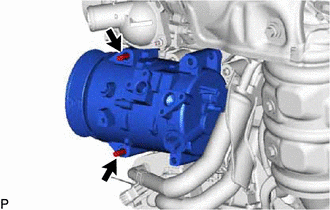
Using an E8 "TORX" socket wrench, remove the 2 stud bolts.
-
-
for Type B:
-
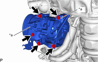
*a Bracket Remove the 5 bolts and separate the 2 brackets.
-
-
Remove the compressor assembly with pulley.
-