CAN COMMUNICATION SYSTEM TERMINALS OF ECU
Note
-
After turning the engine switch off, waiting time may be required before disconnecting the cable from the negative (-) battery terminal. Therefore, make sure to read the disconnecting the cable from the negative (-) battery terminal notices before proceeding with work.
-
Before measuring the resistance of the CAN bus, turn the engine switch off and leave the vehicle for 1 minute or more without operating the key or any switches, or opening or closing the doors. After that, disconnect the cable from the negative (-) battery terminal and leave the vehicle for 1 minute or more before measuring the resistance.
-
This section describes the standard values for all CAN related components.
Tech Tips
-
The systems (ECUs and sensors) that use CAN communication vary depending on the vehicle and optional equipment. Check which systems (ECUs and sensors) are installed to the vehicle.
-
Operating the engine switch, any other switches or a door triggers related ECU and sensor communication on the CAN. This communication will cause the resistance value to change.
-
Even after DTCs are cleared, if a DTC is stored again after driving the vehicle for a while, the malfunction may be occurring due to vibration of the vehicle. In such a case, wiggling the ECUs or wire harness while performing the inspection below may help determine the cause of the malfunction.
-
NO. 1 CAN JUNCTION CONNECTOR
-
Check the No. 1 CAN junction connector.
-
Connection diagram
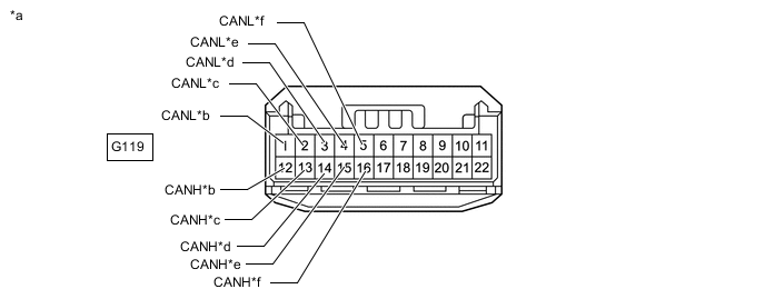
*a Front view of wire harness connector
(to No. 1 CAN Junction Connector)
*b for Radio Receiver Assembly *c for Central Gateway ECU (Network Gateway ECU) *d for No. 21 CAN Junction Connector *e for Bus Buffer ECU (w/ Bus Buffer ECU) *f for Telematics Transceiver (w/ Telematics Transceiver) -
Check the connection diagram of the components which are connected to the No. 1 CAN junction connector.
Terminal No. Wiring Color Connected to G119-12 (CANH) R Radio receiver assembly G119-1 (CANL) W G119-13 (CANH) L Central gateway ECU (network gateway ECU) G119-2 (CANL) W G119-14 (CANH) P No. 21 CAN junction connector G119-3 (CANL) W G119-15 (CANH) Y Bus buffer ECU*1 G119-4 (CANL) W G119-16 (CANH) G Telematics transceiver*2 G119-5 (CANL) W *1: w/ Bus Buffer ECU
*2: w/ Telematics Transceiver
-
-
-
NO. 2 CAN JUNCTION CONNECTOR
-
Check the No. 2 CAN junction connector.
-
Connection diagram
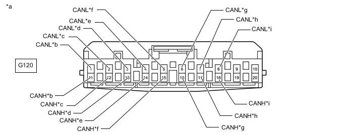
*a Front view of wire harness connector
(to No. 2 CAN Junction Connector)
*b
-
for Combination Meter Assembly (for LHD)
-
for Central Gateway ECU (Network Gateway ECU) (for RHD)
*c
-
for Meter Mirror Sub-assembly (for LHD with Headup Display System)
-
for Certification ECU (Smart Key ECU Assembly) (for RHD)
*d
-
for Certification ECU (Smart Key ECU Assembly) (for LHD)
-
for Meter Mirror Sub-assembly (for RHD with Headup Display System)
*e
-
for Air Conditioning Amplifier Assembly (for LHD)
-
for Multiplex Tilt and Telescopic ECU (for RHD)
*f for Main Body ECU (Multiplex Network Body ECU) *g
-
for Multiplex Tilt and Telescopic ECU (for LHD)
-
for Air Conditioning Amplifier Assembly (for RHD)
*h for No. 11 CAN Junction Connector *i for Headlight ECU Sub-assembly LH (for RHD) - - -
-
Check the connection diagram of the components which are connected to the No. 2 CAN junction connector.
Terminal No. (Symbol) Wiring Color Connected to G120-11 (CANH) Y*1, R*2
-
Combination meter assembly*1
-
Central gateway ECU (network gateway ECU)*2
G120-1 (CANL) W G120-12 (CANH) BE*1, G*2
-
Meter mirror sub-assembly*1*3
-
Certification ECU (smart key ECU assembly)*2
G120-2 (CANL) W G120-13 (CANH) G*1, BE*2
-
Certification ECU (smart key ECU assembly)*1
-
Meter mirror sub-assembly*2*3
G120-3 (CANL) W G120-14 (CANH) L*1, P*2
-
Air conditioning amplifier assembly*1
-
Multiplex tilt and telescopic ECU*2
G120-4 (CANL) W G120-15 (CANH) BE Main body ECU (multiplex network body ECU) G120-5 (CANL) W G120-16 (CANH) P*1, L*2
-
Multiplex tilt and telescopic ECU*1
-
Air conditioning amplifier assembly*2
G120-6 (CANL) W G120-17 (CANH) BR No. 11 CAN junction connector G120-7 (CANL) W G120-18 (CANH) V Headlight ECU sub-assembly LH*2 G120-8 (CANL) W *1: for LHD
*2: for RHD
*3: w/ Headup Display System
-
-
-
-
NO. 4 CAN JUNCTION CONNECTOR
-
Check the No. 4 CAN junction connector.
-
Connection diagram
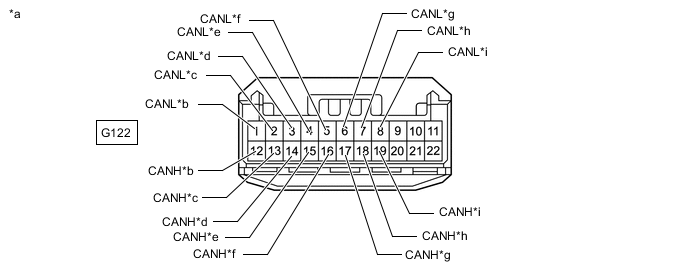
*a Front view of wire harness connector
(to No. 4 CAN Junction Connector)
*b for No. 12 CAN Junction Connector *c for Central Gateway ECU (Network Gateway ECU) *d for Steering Sensor *e for No. 14 CAN Junction Connector *f for Airbag ECU Assembly *g for Yaw Rate Sensor *h for Pedestrian Detection ECU Assembly *i for Front Steering Control ECU (w/ Variable Gear Ratio Steering System) - - -
Check the connection diagram of the components which are connected to the No. 4 CAN junction connector.
Terminal No. (Symbol) Wiring Color Connected to G122-12 (CANH) BR No. 12 CAN junction connector G122-1 (CANL) W G122-13 (CANH) Y Central gateway ECU (network gateway ECU) G122-2 (CANL) W G122-14 (CANH) G Steering sensor G122-3 (CANL) W G122-15 (CANH) LG No. 14 CAN junction connector G122-4 (CANL) W G122-16 (CANH) Y Airbag ECU assembly G122-5 (CANL) W G122-17 (CANH) V Yaw rate sensor G122-6 (CANL) W G122-18 (CANH) P Pedestrian detection ECU assembly G122-7 (CANL) W G122-19 (CANH) BE Front steering control ECU* G122-8 (CANL) W *: w/ Variable Gear Ratio Steering System
-
-
-
NO. 5 CAN JUNCTION CONNECTOR
-
Check the No. 5 CAN junction connector.
-
Connection diagram
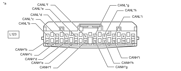
*a Front view of wire harness connector
(to No. 5 CAN Junction Connector)
*b
-
for No. 15 CAN Junction Connector (for LHD)
-
for No. 10 CAN Junction Terminal (for RHD)
*c
-
for Rack and Pinion Power Steering Gear Assembly (for LHD)
-
for Front Steering Control ECU (for RHD with Variable Gear Ratio Steering System)
*d for Driving Support ECU Assembly (w/ Pre-collision System) *e
-
for Rack and Pinion Power Steering Gear Assembly (for RHD)
-
for Front Active Stabilizer Control ECU Assembly (for LHD with Active Stabilizer Suspension System)
*f
-
for Brake Actuator Assembly (Skid Control ECU) (for LHD with Vacuum Brake Booster)
-
for Skid Control ECU Assembly (Skid Control ECU) (for LHD without Vacuum Brake Booster)
-
for Front Active Stabilizer Control ECU Assembly (for RHD with Active Stabilizer Suspension System)
*g for Front Steering Control ECU (for LHD with Variable Gear Ratio Steering System) *h for No. 15 CAN Junction Connector (for RHD) *i
-
for No. 10 CAN Junction Terminal (for LHD)
-
for Brake Actuator Assembly (Skid Control ECU) (for RHD without Vacuum Brake Booster)
- - -
-
Check the connection diagram of the components which are connected to the No. 5 CAN junction connector.
Terminal No. (Symbol) Wiring Color Connected to L123-11 (CANH) B*1, R*2
-
No. 15 CAN junction connector*1
-
No. 10 CAN junction terminal*2
L123-1 (CANL) W L123-12 (CANH) G*1, P*2
-
Rack and pinion power steering gear assembly*1
-
Front steering control ECU*2*3
L123-2 (CANL) W L123-13 (CANH) Y Driving support ECU assembly*4 L123-3 (CANL) W L123-14 (CANH) BE*1, G*2
-
Front active stabilizer control ECU assembly*1*7
-
Rack and pinion power steering gear assembly*2
L123-4 (CANL) W L123-15 (CANH) L*1, BE*2
-
Brake actuator assembly (skid control ECU)*1*5
-
Skid control ECU assembly (skid control ECU)*6
-
Front active stabilizer control ECU assembly*2*7
L123-5 (CANL) W L123-16 (CANH) P Front steering control ECU*1*3 L123-6 (CANL) W L123-17 (CANH) B No. 15 CAN junction connector*2 L123-7 (CANL) W L123-18 (CANH) R*1, L*2
-
No. 10 CAN junction terminal*1
-
Brake actuator assembly (skid control ECU)*2*5
L123-8 (CANL) W *1: for LHD
*2: for RHD
*3: w/ Variable Gear Ratio Steering System
*4: w/ Pre-collision System
*5: w/ Vacuum Brake Booster
*6: for LHD without Vacuum Brake Booster
*7: w/ Active Stabilizer Suspension System
-
-
-
-
NO. 6 CAN JUNCTION CONNECTOR
-
Check the No. 6 CAN junction connector.
-
Connection diagram
*a Front view of wire harness connector
(to No. 6 CAN Junction Connector)
*b for No. 16 CAN Junction Connector *c for Driving Support ECU Assembly (for RHD with Pre-collision System) *d for Millimeter Wave Radar Sensor Assembly (w/ Pre-collision System) *e for No. 7 CAN Junction Connector *f for Central Gateway ECU (Network Gateway ECU) (for RHD) *g for Parking Assist ECU (w/ Panoramic View Monitor System) - - -
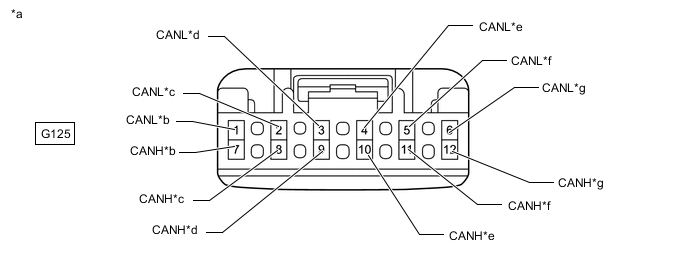
Check the connection diagram of the components which are connected to the No. 6 CAN junction connector.
Terminal No. (Symbol) Wiring Color Connected to G125-7 (CANH) B No. 16 CAN junction connector G125-1 (CANL) W G125-8 (CANH) R Driving support ECU assembly**1*2 G125-2 (CANL) W G125-9 (CANH) V Millimeter wave radar sensor assembly*2 G125-3 (CANL) W G125-10 (CANH) G No. 7 CAN junction connector G125-4 (CANL) W G125-11 (CANH) BE Central gateway ECU (network gateway ECU)*1 G125-5 (CANL) W G125-12 (CANH) L Parking assist ECU*3 G125-6 (CANL) W *1: for RHD
*2: w/ Pre-collision System
*3: w/ Panoramic View Monitor System
-
-
-
NO. 7 CAN JUNCTION CONNECTOR
-
Check the No. 7 CAN junction connector.
-
Connection diagram
*a Front view of wire harness connector
(to NO. 7 CAN Junction Connector)
*b for Central Gateway ECU (Network Gateway ECU) (for LHD) *c for No. 9 CAN Junction Terminal *d for Forward Recognition Camera (w/ Pre-collision System) *e for Driving Support ECU Assembly (for LHD with Pre-collision System) *f for No. 6 CAN Junction Connector -
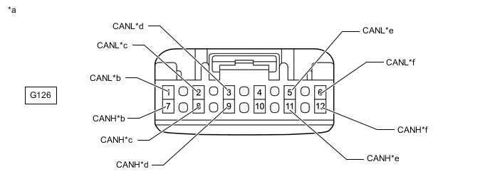
Check the connection diagram of the components which are connected to the No. 7 CAN junction connector.
Terminal No. (Symbol) Wiring Color Connected to G126-7 (CANH) BE Central gateway ECU (network gateway ECU)*1 G126-1 (CANL) W G126-8 (CANH) Y No. 9 CAN junction terminal G126-2 (CANL) W G126-9 (CANH) V Forward recognition camera*2 G126-3 (CANL) W G126-11 (CANH) R Driving support ECU assembly*1*2 G126-5 (CANL) W G126-12 (CANH) G No. 6 CAN junction connector G126-6 (CANL) W *1: for LHD
*2: w/ Pre-collision System
-
-
-
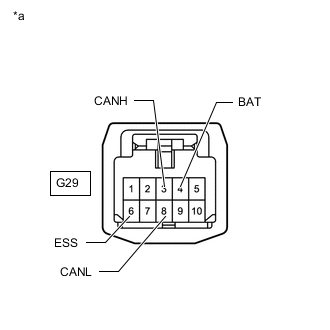
NO. 9 CAN JUNCTION CONNECTOR
-
Check the No. 9 CAN junction connector.
-
Connection diagram
*a Front view of wire harness connector
(to No. 9 CAN Junction Connector)
*b for Central Gateway ECU (Network Gateway ECU) *c for Engine Stop and Start ECU (w/ Stop and Start System) *d for Shift Control ECU *e for No. 13 CAN Junction Connector - - -
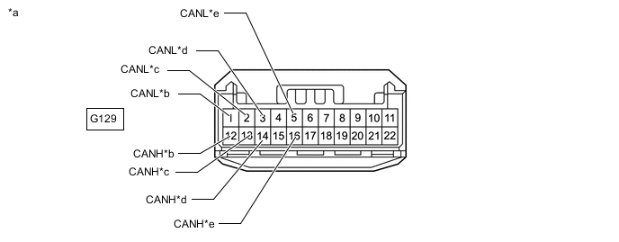
Check the connection diagram of the components which are connected to the No. 9 CAN junction connector.
Terminal No. (Symbol) Wiring Color Connected to G129-12 (CANH) R Central gateway ECU (network gateway ECU) G129-1 (CANL) W G129-13 (CANH) L Engine stop and start ECU* G129-2 (CANL) W G129-14 (CANH) Y Shift control ECU G129-3 (CANL) W G129-16 (CANH) BR No. 13 CAN junction connector G129-5 (CANL) W *: w/ Stop and Start System
-
-
-
NO. 10 CAN JUNCTION CONNECTOR
-
Check the No. 10 CAN junction connector.
-
Connection diagram
*a Front view of wire harness connector
(to No. 10 CAN Junction Connector)
*b for Front Multiplex Network Door ECU RH *c
-
for No. 2 Position Control ECU Assembly (for LHD)
-
for Position Control ECU Assembly (for RHD)
*d
-
for Central Gateway ECU (Network Gateway ECU) (for LHD)
-
for Combination Meter Assembly (for RHD)
*e for No. 11 CAN Junction Connector *f for Headlight ECU Sub-assembly LH (for LHD) *g for Headlight ECU Sub-assembly RH (for LHD) - - -
-
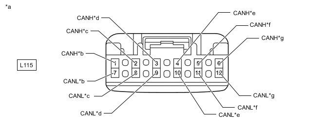
Check the connection diagram of the components which are connected to the No. 10 CAN junction connector.
Terminal No. (Symbol) Wiring Color Connected to L115-1 (CANH) GR Front multiplex network door ECU RH L115-7 (CANL) W L115-2 (CANH) SB
-
No. 2 position control ECU assembly*1
-
Position control ECU assembly*2
L115-8 (CANL) W L115-3 (CANH) Y
-
Central gateway ECU (network gateway ECU)*1
-
Combination meter assembly*2
L115-9 (CANL) W L115-4 (CANH) R No. 11 CAN junction connector L115-10 (CANL) W L115-5 (CANH) V Headlight ECU sub-assembly LH*1 L115-11 (CANL) W L115-6 (CANH) B Headlight ECU sub-assembly RH*1 L115-12 (CANL) W *1: for LHD
*2: for RHD
-
-
-
-
NO. 11 CAN JUNCTION CONNECTOR
-
Check the No. 11 CAN junction connector.
-
Connection diagram
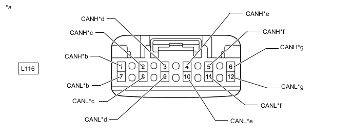
*a Front view of wire harness connector
(to No. 11 CAN Junction Connector)
*b for No. 2 CAN Junction Connector *c for Front Multiplex Network Door ECU LH *d for No. 10 CAN Junction Connector *e
-
Position Control ECU Assembly (for LHD)
-
No. 2 Position Control ECU Assembly (for RHD)
*f for Rear Power Seat Switch (Rear Multi Operation Panel) (w/ Rear Multi Operation Panel System) *g for Headlight ECU Sub-assembly RH (for RHD) - - -
-
Check the connection diagram of the components which are connected to the No. 11 CAN junction connector.
Terminal No. (Symbol) Wiring Color Connected to L116-1 (CANH) BR No. 2 CAN junction connector L116-7 (CANL) W L116-2 (CANH) GR Front multiplex network door ECU LH L116-8 (CANL) W L116-3 (CANH) R No. 10 CAN junction connector L116-9 (CANL) W L116-4 (CANH) Y
-
Position control ECU assembly*1
-
No. 2 position control ECU assembly*2
L116-10 (CANL) W L116-5 (CANH) P Rear power seat switch (rear multi operation panel)*3 L116-11 (CANL) W L116-6 (CANH) B Headlight ECU sub-assembly RH*2 L116-12 (CANL) W *1: for LHD
*2: for RHD
*3: w/ Rear Multi Operation Panel System
-
-
-
-
NO. 12 CAN JUNCTION CONNECTOR
-
Check the No. 12 CAN junction connector.
-
Connection diagram
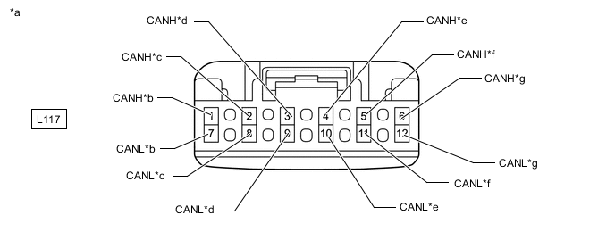
*a Front view of wire harness connector
(to No. 12 CAN Junction Connector)
*b
-
for Brake Actuator Assembly (Skid Control ECU) (for LHD with Vacuum Brake Booster)
-
for Skid Control ECU Assembly (Skid Control ECU) (for LHD without Vacuum Brake Booster)
-
for No. 4 CAN Junction Connector (for RHD)
*c
-
for No. 4 CAN Junction Connector (for LHD)
-
for No. 2 CAN Junction Terminal (for RHD)
*d
-
for No. 2 CAN Junction Terminal (for LHD)
-
for Front Active Stabilizer Control ECU Assembly (for RHD with Active Stabilizer Suspension System)
*e
-
for Rack and Pinion Power Steering Gear Assembly (for RHD)
-
for Front Active Stabilizer Control ECU Assembly (for LHD with Active Stabilizer Suspension System)
*f for Rack and Pinion Power Steering Gear Assembly (for LHD) *g for Brake Actuator Assembly (Skid Control ECU) (for RHD with Vacuum Brake Booster) - - -
-
Check the connection diagram of the components which are connected to the No. 12 CAN junction connector.
Terminal No. (Symbol) Wiring Color Connected to L117-1 (CANH) GR*1, BR*2
-
Brake actuator assembly (skid control ECU)*1*3
-
Skid control ECU assembly (skid control ECU)*4
-
No. 4 CAN junction connector*2
L117-7 (CANL) W L117-2 (CANH) BR*1, B*2
-
No. 4 CAN junction connector*1
-
No. 2 CAN junction terminal*2
L117-8 (CANL) W L117-3 (CANH) B*1, G*2
-
No. 2 CAN junction terminal*1
-
Front active stabilizer control ECU assembly*2*5
L117-9 (CANL) W L117-4 (CANH) G*1, P*2
-
Front active stabilizer control ECU assembly*1*5
-
Rack and pinion power steering gear assembly*2
L117-10 (CANL) W L117-5 (CANH) P Rack and pinion power steering gear assembly*1 L117-11 (CANL) W L117-6 (CANH) GR Brake actuator assembly (skid control ECU)*2*3 L117-12 (CANL) W *1: for LHD
*2: for RHD
*3: w/ Vacuum Brake Booster
*4: for LHD without Vacuum Brake Booster
*5: w/ Active Stabilizer Suspension System
-
-
-
-
NO. 13 CAN JUNCTION CONNECTOR
-
Check the No. 13 CAN junction connector.
-
Connection diagram
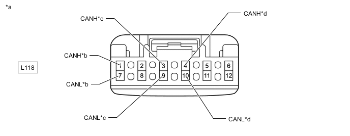
*a Front view of wire harness connector
(to No. 13 CAN Junction Connector)
*b for ECM *c for No. 9 CAN Junction Connector *d for Sub-battery with Control Assembly -
Check the connection diagram of the components which are connected to the No. 13 CAN junction connector.
Terminal No. (Symbol) Wiring Color Connected to L118-1 (CANH) GR ECM L118-7 (CANL) W L118-3 (CANH) BR No. 9 CAN junction connector L118-9 (CANL) W L118-4 (CANH) LG Sub-battery with control assembly L118-10 (CANL) W
-
-
-
NO. 14 CAN JUNCTION CONNECTOR
-
Check the No. 14 CAN junction connector.
-
Connection diagram
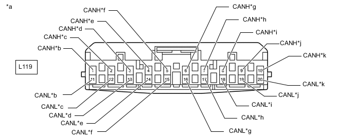
*a Front view of wire harness connector
(to No. 14 CAN Junction Connector)
*b for No. 1 CAN Junction Terminal *c for No. 4 CAN Junction Connector *d for Parking Brake ECU Assembly *e for Absorber Control ECU (w/ Adaptive Variable Suspension System) *f for Tire Pressure Warning ECU and Receiver *g for Rear Active Stabilizer Control ECU Assembly (for LHD with Active Stabilizer Suspension System) *h for Suspension Control ECU (w/ Air Suspension System) *i for Rear Steering Control ECU (w/ Dynamic Rear Steering System) *j for Occupant Detection ECU (w/ Occupant Classification System) *k for Rear Active Stabilizer Control ECU Assembly (for RHD with Active Stabilizer Suspension System) - - -
Check the connection diagram of the components which are connected to the No. 14 CAN junction connector.
Terminal No. (Symbol) Wiring Color Connected to L119-1 (CANH) B No. 1 CAN junction terminal L119-11 (CANL) W L119-2 (CANH) LG No. 4 CAN junction connector L119-12 (CANL) W L119-3 (CANH) L Parking brake ECU assembly L119-13 (CANL) W L119-4 (CANH) SB Absorber control ECU*3 L119-14 (CANL) W L119-5 (CANH) Y Tire pressure warning ECU and receiver L119-15 (CANL) W L119-6 (CANH) P Rear active stabilizer control ECU assembly*1*7 L119-16 (CANL) W L119-7 (CANH) G Suspension control ECU*4 L119-17 (CANL) W L119-8 (CANH) V Rear steering control ECU*5 L119-18 (CANL) W L119-9 (CANH) BE Occupant detection ECU*6 L119-19 (CANL) W L119-10 (CANH) P Rear active stabilizer control ECU assembly*2*7 L119-20 (CANL) W *1: for LHD
*2: for RHD
*3: w/ Adaptive Variable Suspension System
*4: w/ Air Suspension System
*5: w/ Dynamic Rear Steering System
*6: w/ Occupant Classification System
*7: w/ Active Stabilizer Suspension System
-
-
-
NO. 15 CAN JUNCTION CONNECTOR
-
Check the No. 15 CAN junction connector.
-
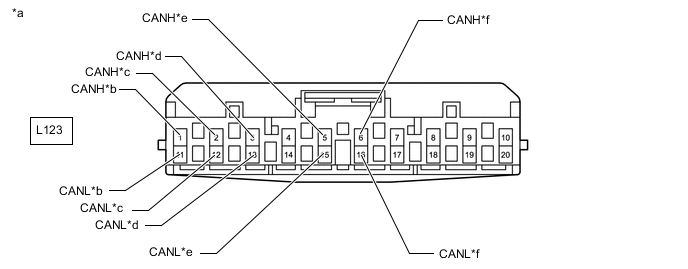
Connection diagram
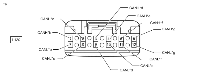
*a Front view of wire harness connector
(to No. 15 CAN Junction Connector)
*b for Suspension Control ECU (w/ Air Suspension System) *c for Absorber Control ECU (w/ Adaptive Variable Suspension System) *d for No. 8 CAN Junction Terminal *e for No. 5 CAN Junction Connector *f for Rear Steering Control ECU (w/ Dynamic Rear Steering System) *g for Rear Active Stabilizer Control ECU Assembly (w/ Active Stabilizer Suspension System) - - -
Check the connection diagram of the components which are connected to the No. 15 CAN junction connector.
Terminal No. (Symbol) Wiring Color Connected to L120-1 (CANH) V Suspension control ECU*1 L120-7 (CANL) W L120-2 (CANH) R Absorber control ECU*2 L120-8 (CANL) W L120-3 (CANH) B No. 8 CAN junction terminal L120-9 (CANL) W L120-4 (CANH) B No. 5 CAN junction connector L120-10 (CANL) W L120-5 (CANH) Y Rear steering control ECU*3 L120-11 (CANL) W L120-6 (CANH) G Rear active stabilizer control ECU assembly*4 L120-12 (CANL) W *1: w/ Air Suspension System
*2: w/ Adaptive Variable Suspension System
*3: w/ Dynamic Rear Steering System
*4: w/ Active Stabilizer Suspension System
-
-
-
NO. 16 CAN JUNCTION CONNECTOR
-
Check the No. 16 CAN junction connector.
-
Connection diagram
*a Front view of wire harness connector
(to No. 16 CAN Junction Connector)
*b for No. 6 CAN Junction Connector *c for No. 3 CAN Junction Terminal *d for Clearance Warning ECU Assembly *e for Rear Television Camera Assembly *f for Blind Spot Monitor Sensor RH (w/ Blind Spot Monitor System) -
Check the connection diagram of the components which are connected to the No. 16 CAN junction connector.
Terminal No. (Symbol) Wiring Color Connected to L123-1 (CANH) B No. 6 CAN junction connector L123-11 (CANL) W L123-2 (CANH) Y No. 3 CAN junction terminal L123-12 (CANL) W L123-3 (CANH) BE Clearance warning ECU assembly L23-13 (CANL) W L123-5 (CANH) P Rear television camera assembly L123-15 (CANL) W L123-6 (CANH) LG Blind spot monitor sensor RH* L123-16 (CANL) W *: w/ Blind Spot Monitor System
-
-
-
NO. 21 CAN JUNCTION CONNECTOR
-
Check the No. 21 CAN junction connector.
-
Connection diagram
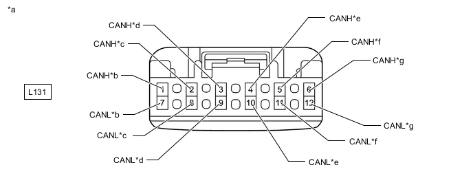
*a Front view of wire harness connector
(to No. 21 CAN Junction Connector)
*b for No. 1 CAN Junction Connector *c for Luggage Closer Motor Assembly *d for Rear Multiplex Network Door ECU LH *e for Stereo Component Equalizer Assembly *f for No. 7 CAN Junction Terminal *g for Rear Multiplex Network Door ECU RH - - -
Check the connection diagram of the components which are connected to the No. 21 CAN junction connector.
Terminal No. (Symbol) Wiring Color Connected to L131-1 (CANH) P No. 1 CAN junction connector L131-7 (CANL) W L131-2 (CANH) R Luggage closer motor assembly L131-8 (CANL) W L131-3 (CANH) SB Rear multiplex network door ECU LH L131-9 (CANL) W L131-4 (CANH) G Stereo component equalizer assembly L131-10 (CANL) W L131-5 (CANH) B No. 7 CAN junction terminal L131-11 (CANL) W L131-6 (CANH) V Rear multiplex network door ECU RH L131-12 (CANL) W
-
-
-
NO. 1 CAN JUNCTION TERMINAL
-
Check the No. 1 CAN junction terminal.
-

*a Rear view of wire harness connector
(to No. 1 CAN Junction Terminal)
*b for No. 14 CAN Junction Connector Connection diagram
-
Check the connection diagram of the components which are connected to the No. 1 CAN junction terminal.
Terminal No. (Symbol) Wiring Color Connected to L121-3 (CANH) B No. 14 CAN junction connector L121-2 (CANL) W
-
-
-
NO. 2 CAN JUNCTION TERMINAL
-
Check the No. 2 CAN junction terminal.
-
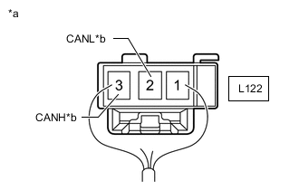
*a Rear view of wire harness connector
(to No. 2 CAN Junction Terminal)
*b for No. 12 CAN Junction Connector Connection diagram
-
Check the connection diagram of the components which are connected to the No. 2 CAN junction terminal.
Terminal No. (Symbol) Wiring Color Connected to L122-3 (CANH) B No. 12 CAN junction connector L122-2 (CANL) W
-
-
-
NO. 3 CAN JUNCTION TERMINAL
-
Check the No. 3 CAN junction terminal.
-
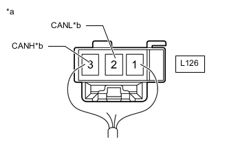
*a Rear view of wire harness connector
(to No. 3 CAN Junction Terminal)
*b for No. 16 CAN Junction Connector Connection diagram
-
Check the connection diagram of the components which are connected to the No. 3 CAN junction terminal.
Terminal No. (Symbol) Wiring Color Connected to L126-3 (CANH) Y No. 16 CAN junction connector L126-2 (CANL) W
-
-
-
NO. 7 CAN JUNCTION TERMINAL
-
Check the No. 7 CAN junction terminal.
-

*a Rear view of wire harness connector
(to No. 7 CAN Junction Terminal)
*b for No. 21 CAN Junction Connector Connection diagram
-
Check the connection diagram of the components which are connected to the No. 7 CAN junction terminal.
Terminal No. (Symbol) Wiring Color Connected to L132-3 (CANH) B No. 21 CAN junction connector L132-2 (CANL) W
-
-
-
NO. 8 CAN JUNCTION TERMINAL
-
Check the No. 8 CAN junction terminal.
-

*a Rear view of wire harness connector
(to No. 8 CAN Junction Terminal)
*b for No. 15 CAN Junction Connector Connection diagram
-
Check the connection diagram of the components which are connected to the No. 8 CAN junction terminal.
Terminal No. (Symbol) Wiring Color Connected to L133-3 (CANP) B No. 15 CAN junction connector L133-2 (CANN) W
-
-
-
NO. 9 CAN JUNCTION TERMINAL
-
Check the No. 9 CAN junction terminal.
-

*a Rear view of wire harness connector
(to No. 9 CAN Junction Terminal)
*b for No. 7 CAN Junction Connector Connection diagram
-
Check the connection diagram of the components which are connected to the No. 9 CAN junction terminal.
Terminal No. (Symbol) Wiring Color Connected to G127-3 (CANH) Y No. 7 CAN junction connector G127-2 (CANL) W
-
-
-
NO. 10 CAN JUNCTION TERMINAL
-
Check the No. 10 CAN junction terminal.
-
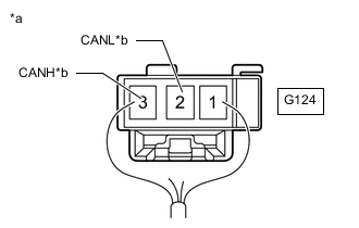
*a Rear view of wire harness connector
(to No. 10 CAN Junction Terminal)
*b for No. 5 CAN Junction Connector Connection diagram
-
Check the connection diagram of the components which are connected to the No. 10 CAN junction terminal.
Terminal No. (Symbol) Wiring Color Connected to G124-3 (CANH) R No. 5 CAN junction connector G124-2 (CANL) W
-
-
-
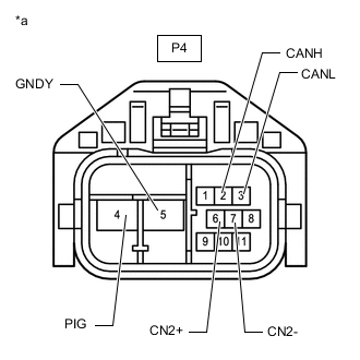
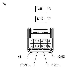
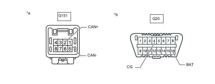
DLC3
-
Disconnect the cable from the negative (-) battery terminal.
-
Measure the resistance according to the value(s) in the table below.
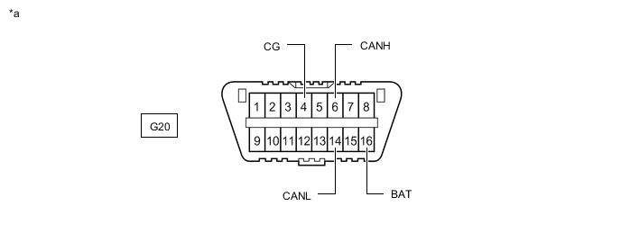
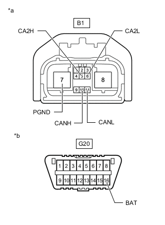
*a Front view of DLC3 - -
-
-
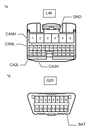
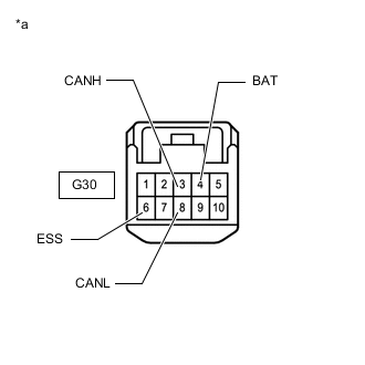
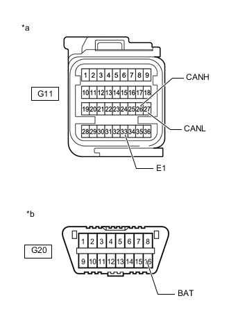
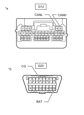
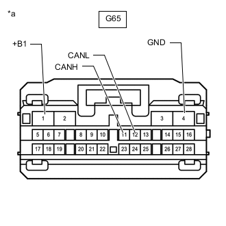
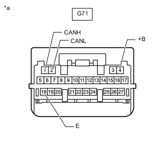
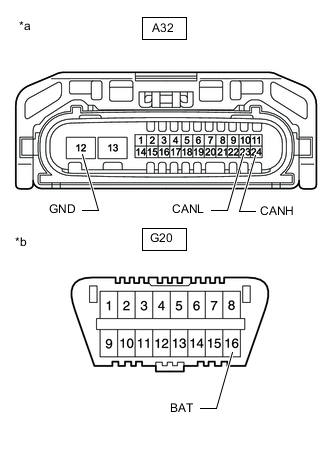
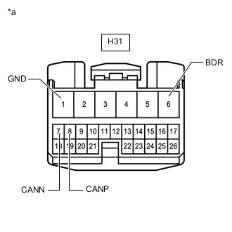
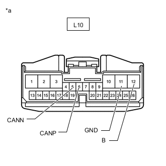
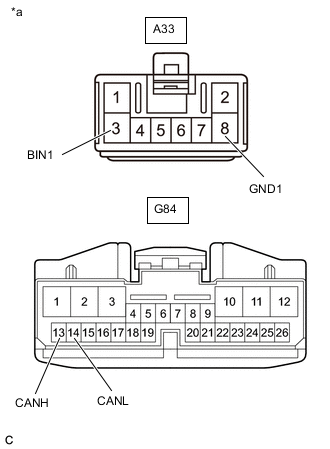
CENTRAL GATEWAY ECU (NETWORK GATEWAY ECU)
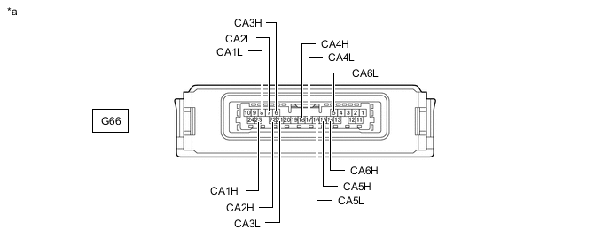
*a Component without harness connected
(Central Gateway ECU [Network Gateway ECU])
- -
-
Disconnect the cable from the negative (-) battery terminal.
-
Disconnect the central gateway ECU (network gateway ECU) connector.
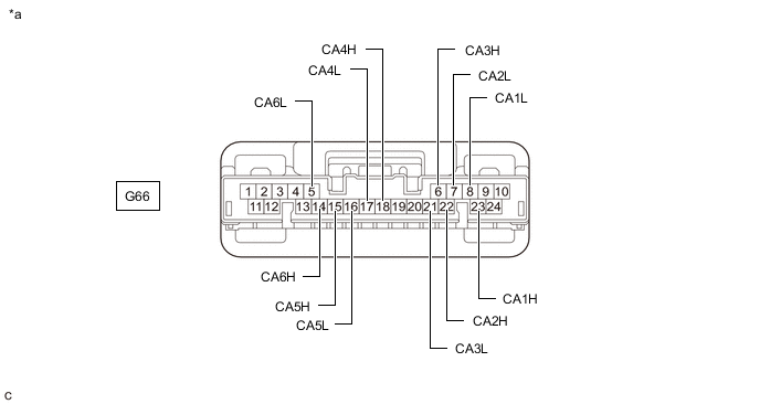
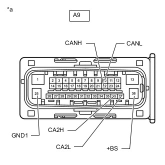
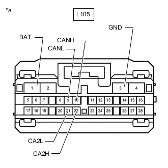
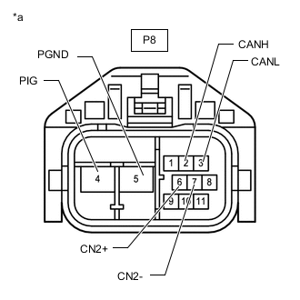
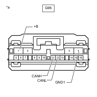
*a Front view of wire harness connector
(to Central Gateway ECU [Network Gateway ECU])
- - -
Measure the resistance according to the value(s) in the table below.
-
-
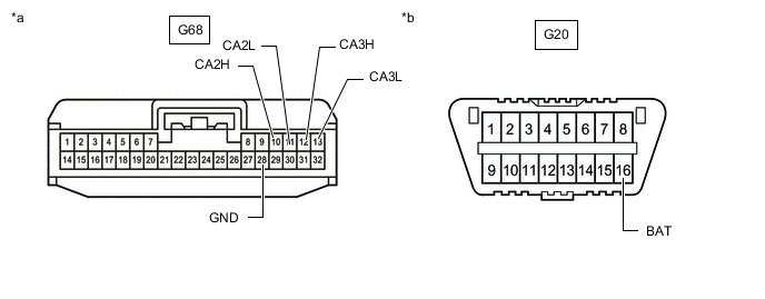
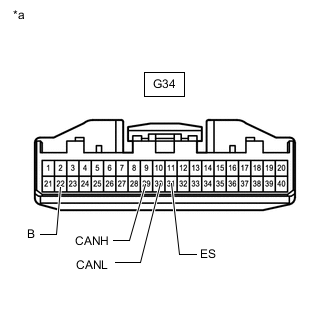
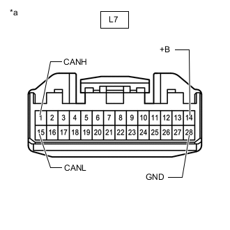
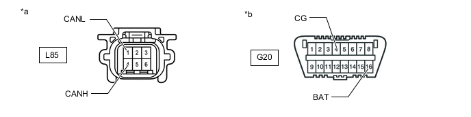
ECM (for 8GR-FKS)
Refer to Terminals of ECU.
-
Disconnect the cable from the negative (-) battery terminal.
-
Disconnect the ECM connectors.
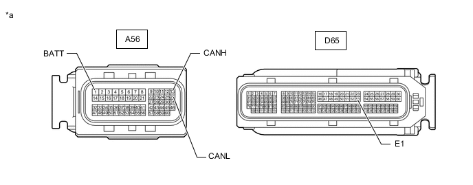
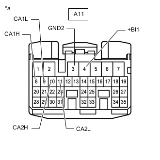
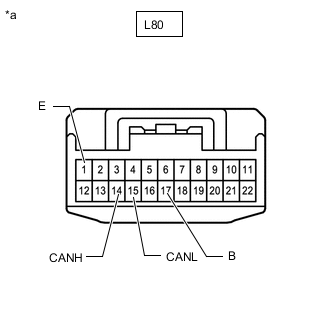
*a Front view of wire harness connector
(to ECM)
- - -
Measure the resistance according to the value(s) in the table below.
-
-
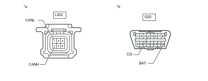
ECM (for V35A-FTS)
Refer to Terminals of ECU.
w/ Canister Pump Module: Click here
w/o Canister Pump Module: Click here
-
Disconnect the cable from the negative (-) battery terminal.
-
Disconnect the ECM connectors.
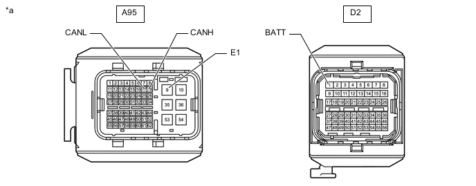
*a Front view of wire harness connector
(to ECM)
- - -
Measure the resistance according to the value(s) in the table below.
-
-
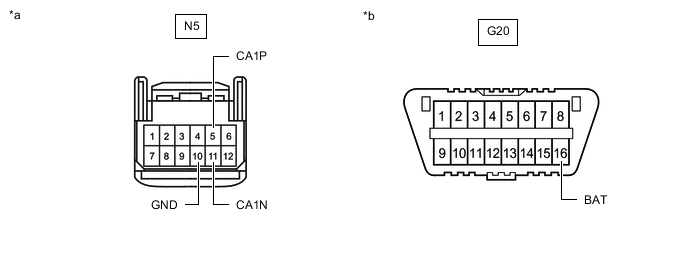
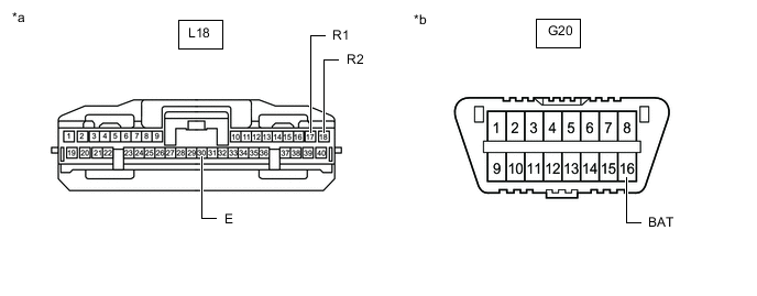
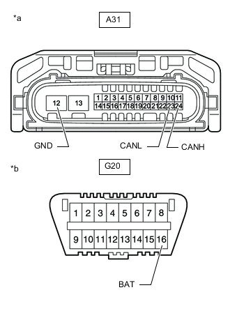
SHIFT CONTROL ECU
Refer to Terminals of ECU.
for 2WD (for 8GR-FKS): Click here
for 2WD (for V35A-FTS): Click here
for AWD: Click here
-
Disconnect the cable from the negative (-) battery terminal.
-
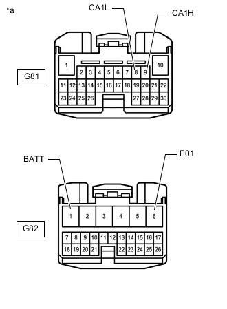
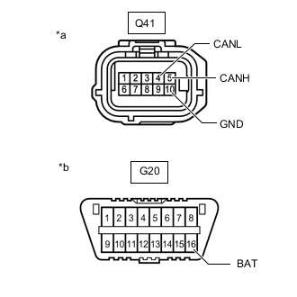
*a Front view of wire harness connector
(to Shift Control ECU)
Disconnect the shift control ECU connectors.
-
Measure the resistance according to the value(s) in the table below.
-
-
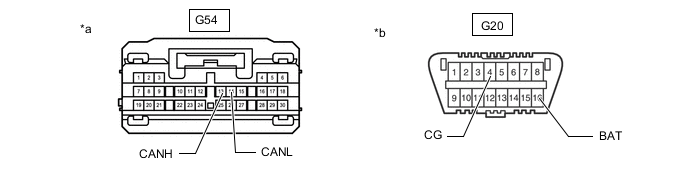
BRAKE ACTUATOR ASSEMBLY (SKID CONTROL ECU) (w/ Vacuum Brake Booster)
Refer to Terminals of ECU.
-
Disconnect the cable from the negative (-) battery terminal.
-
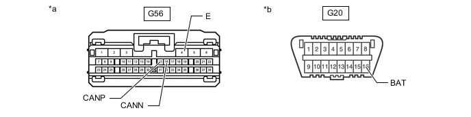
*a Front view of wire harness connector
(to Brake Actuator Assembly [skid control ECU])
Disconnect the brake actuator assembly (skid control ECU) connector.
-
Measure the resistance according to the value(s) in the table below.
-
-
SKID CONTROL ECU ASSEMBLY (SKID CONTROL ECU) (w/o Vacuum Brake Booster)
Refer to Terminals of ECU.
-
Disconnect the cable from the negative (-) battery terminal.
-
*a Front view of wire harness connector
(to Skid Control ECU Assembly [Skid Control ECU])
Disconnect the skid control ECU assembly (skid control ECU) connectors.
-
Measure the resistance according to the value(s) in the table below.
-
-
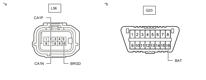
RACK AND PINION POWER STEERING GEAR ASSEMBLY
Refer to Terminals of ECU.
-
Disconnect the cable from the negative (-) battery terminal.
-
*a Front view of wire harness connector
(to Rack and Pinion Power Steering Gear Assembly)
*b Front view of DLC3 Disconnect the rack and pinion power steering gear assembly connector.
-
Measure the resistance according to the value(s) in the table below.
-
-
FRONT STEERING CONTROL ECU (w/ Variable Gear Ratio Steering System)
Refer to Terminals of ECU.
-
Disconnect the cable from the negative (-) battery terminal.
-
*a Front view of wire harness connector
(to Front Steering Control ECU)
Disconnect the front steering control ECU connector.
-
Measure the resistance according to the value(s) in the table below.
-
-
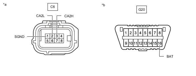
REAR STEERING CONTROL ECU (w/ Dynamic Rear Steering System)
Refer to Terminals of ECU.
-
Disconnect the cable from the negative (-) battery terminal.
-
*a Front view of wire harness connector
(to Rear Steering Control ECU)
Disconnect the rear steering control ECU connector.
-
Measure the resistance according to the value(s) in the table below.
-
-
ABSORBER CONTROL ECU (w/ Adaptive Variable Suspension System)
Refer to Terminals of ECU.
-
Disconnect the cable from the negative (-) battery terminal.
-
*a Front view of wire harness connector
(to Absorber Control ECU)
*b Front view of DLC3 Disconnect the absorber control ECU connector.
-
Measure the resistance according to the value(s) in the table below.
-
-
YAW RATE SENSOR
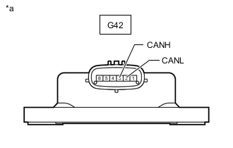
*a Component without harness connected
(Yaw Rate Sensor)
-
Disconnect the cable from the negative (-) battery terminal.
-
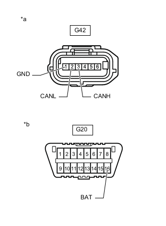
*a Front view of wire harness connector
(to Yaw Rate Sensor)
*b Front view of DLC3 Disconnect the yaw rate sensor connector.
-
Measure the resistance according to the value(s) in the table below.
-
-
SUSPENSION CONTROL ECU (w/ Air Suspension System)
Refer to Terminals of ECU.
-
Disconnect the cable from the negative (-) battery terminal.
-
*a Front view of wire harness connector
(to Suspension Control ECU)
Disconnect the suspension control ECU connector.
-
Measure the resistance according to the value(s) in the table below.
-
-
FRONT ACTIVE STABILIZER CONTROL ECU ASSEMBLY (w/ Active Stabilizer Suspension System)
Refer to Terminals of ECU.
-
Disconnect the cable from the negative (-) battery terminal.
-

*a Front view of wire harness connector
(to Front Active Stabilizer Control ECU Assembly)
Disconnect the front active stabilizer control ECU assembly connector.
-
Measure the resistance according to the value(s) in the table below.
-
-
REAR ACTIVE STABILIZER CONTROL ECU ASSEMBLY (w/ Active Stabilizer Suspension System)
Refer to Terminals of ECU.
-
Disconnect the cable from the negative (-) battery terminal.
-
*a Front view of wire harness connector
(to Rear Active Stabilizer Control ECU Assembly)
Disconnect the rear active stabilizer control ECU assembly connector.
-
Measure the resistance according to the value(s) in the table below.
-
-
PARKING BRAKE ECU ASSEMBLY
Refer to Terminals of ECU.
-
Disconnect the cable from the negative (-) battery terminal.
-
Disconnect the parking brake ECU assembly connectors.
*a Front view of wire harness connector
(to Parking Brake ECU Assembly)
- - -
Measure the resistance according to the value(s) in the table below.
-
-
MULTIPLEX TILT AND TELESCOPIC ECU
Refer to Terminals of ECU.
-
Disconnect the cable from the negative (-) battery terminal.
-
*a Front view of wire harness connector
(to Multiplex Tilt and Telescopic ECU)
Disconnect the multiplex tilt and telescopic ECU connector.
-
Measure the resistance according to the value(s) in the table below.
-
-
STEERING SENSOR (w/ Variable Gear Ratio Steering System)
-
Disconnect the cable from the negative (-) battery terminal.
-
*a Front view of wire harness connector
(to Steering Sensor)
Disconnect the steering sensor connector.
-
Measure the resistance according to the value(s) in the table below.
-
-
STEERING SENSOR (w/o Variable Gear Ratio Steering System)
-
Disconnect the cable from the negative (-) battery terminal.
-
*a Front view of wire harness connector
(to Steering Sensor)
Disconnect the steering sensor connector.
-
Measure the resistance according to the value(s) in the table below.
-
-
DRIVING SUPPORT ECU ASSEMBLY (w/ Pre-collision System)
Refer to Terminals of ECU.
-
Disconnect the cable from the negative (-) battery terminal.
-
Disconnect the driving support ECU assembly connector.
*a Front view of wire harness connector
(to Driving Support ECU Assembly)
*b Front view of DLC3 -
Measure the resistance according to the value(s) in the table below.
-
-
FORWARD RECOGNITION CAMERA (w/ Pre-collision System)
Refer to Terminals of ECU.
-
Disconnect the cable from the negative (-) battery terminal.
-
Disconnect the forward recognition camera connector.
*a Front view of wire harness connector
(to Forward Recognition Camera)
*b Front view of DLC3 -
Measure the resistance according to the value(s) in the table below.
-
-
MILLIMETER WAVE RADAR SENSOR ASSEMBLY (w/ Pre-collision System)
Refer to Terminals of ECU.
-
Disconnect the cable from the negative (-) battery terminal.
-
Disconnect the millimeter wave radar sensor assembly connector.
*a Front view of wire harness connector
(to Millimeter Wave Radar Sensor Assembly)
*b Front view of DLC3 -
Measure the resistance according to the value(s) in the table below.
-
-
AIRBAG ECU ASSEMBLY
Refer to Terminals of ECU.
-
Disconnect the cable from the negative (-) battery terminal, and wait for at least 90 seconds.
-
*a Front view of wire harness connector
(to Airbag ECU Assembly)
*b Front view of DLC3 Disconnect the airbag ECU assembly connector.
-
Measure the resistance according to the value(s) in the table below.
-
-
PEDESTRIAN DETECTION ECU ASSEMBLY
Refer to Terminals of ECU.
-
Disconnect the cable from the negative (-) battery terminal, and wait for at least 90 seconds.
-
*a Front view of wire harness connector
(to Pedestrian detection ECU assembly)
*b Front view of DLC3 Disconnect the pedestrian detection ECU assembly connector.
-
Measure the resistance according to the value(s) in the table below.
-
-
COMBINATION METER ASSEMBLY
Refer to Terminals of ECU.
-
Disconnect the cable from the negative (-) battery terminal.
-
*a Front view of wire harness connector
(to Combination Meter Assembly)
Disconnect the combination meter assembly connector.
-
Measure the resistance according to the value(s) in the table below.
-
-
METER MIRROR SUB-ASSEMBLY (w/ Headup Display System)
Refer to Terminals of ECU.
-
Disconnect the cable from the negative (-) battery terminal.
-
*a Front view of wire harness connector
(to Meter Mirror Sub-assembly)
Disconnect the meter mirror sub-assembly connector.
-
Measure the resistance according to the value(s) in the table below.
-
-
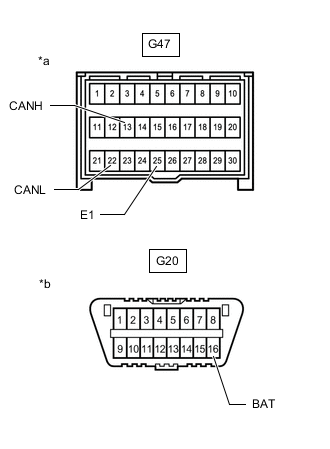
MAIN BODY ECU (MULTIPLEX NETWORK BODY ECU)
Refer to Terminals of ECU.
-
Disconnect the cable from the negative (-) battery terminal.
-
*a Front view of wire harness connector
(to Main Body ECU [Multiplex Network Body ECU])
*b Front view of DLC3 Disconnect the main body ECU (multiplex network body ECU) connector.
-
Measure the resistance according to the value(s) in the table below.
-
-
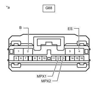
RADIO RECEIVER ASSEMBLY
Refer to Terminals of ECU.
-
Disconnect the cable from the negative (-) battery terminal.
-
Disconnect the radio receiver assembly connectors.
*a Front view of wire harness connector
(to Radio Receiver Assembly)
*b Front view of DLC3 -
Measure the resistance according to the value(s) in the table below.
-
-
STEREO COMPONENT EQUALIZER ASSEMBLY
Refer to Terminals of ECU.
-
Disconnect the cable from the negative (-) battery terminal.
-
*a Front view of wire harness connector
(to Stereo Component Equalizer Assembly)
Disconnect the stereo component equalizer assembly connector.
-
Measure the resistance according to the value(s) in the table below.
-
-
AIR CONDITIONING AMPLIFIER ASSEMBLY
Refer to Terminals of ECU.
-
Disconnect the cable from the negative (-) battery terminal.
-
*a Front view of wire harness connector
(to Air Conditioning Amplifier Assembly)
Disconnect the air conditioning amplifier assembly connector.
-
Measure the resistance according to the value(s) in the table below.
-
-
REAR TELEVISION CAMERA ASSEMBLY (w/ Panoramic View Monitor System)
Refer to Terminals of ECU.
-
Disconnect the cable from the negative (-) battery terminal.
-
Disconnect the rear television camera assembly connector.
*a Front view of wire harness connector
(to Rear Television Camera Assembly)
*b Front view of DLC3 -
Measure the resistance according to the value(s) in the table below.
-
-
REAR TELEVISION CAMERA ASSEMBLY (w/ Parking Assist Monitor System)
Refer to Terminals of ECU.
-
Disconnect the cable from the negative (-) battery terminal.
-
Disconnect the rear television camera assembly connector.
*a Front view of wire harness connector
(to Rear Television Camera Assembly)
*b Front view of DLC3 -
Measure the resistance according to the value(s) in the table below.
-
-
CLEARANCE WARNING ECU ASSEMBLY
Refer to Terminals of ECU.
-
Disconnect the cable from the negative (-) battery terminal.
-
Disconnect the clearance warning ECU assembly connector.
*a Front view of wire harness connector
(to Clearance Warning ECU Assembly)
*b Front view of DLC3 -
Measure the resistance according to the value(s) in the table below.
-
-
BLIND SPOT MONITOR SENSOR RH (w/ Blind Spot Monitor System)
Refer to Terminals of ECU.
-
Disconnect the cable from the negative (-) battery terminal.
-
Disconnect the blind spot monitor sensor RH connector.
*a Front view of wire harness connector
(to Blind Spot Monitor Sensor RH)
*b Front view of DLC3 -
Measure the resistance according to the value(s) in the table below.
-
-
CERTIFICATION ECU (SMART KEY ECU ASSEMBLY)
Refer to Terminals of ECU.
-
Disconnect the cable from the negative (-) battery terminal.
-
*a Front view of wire harness connector
(to Certification ECU [Smart Key ECU Assembly])
Disconnect the certification ECU (smart key ECU assembly) connector.
-
Measure the resistance according to the value(s) in the table below.
-
-
SUB-BATTERY WITH CONTROL ASSEMBLY
Refer to Terminals of ECU.
-
Disconnect the cable from the negative (-) battery terminal.
-
Disconnect the sub-battery with control assembly connector.
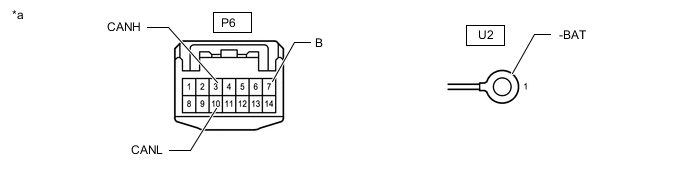
*a Front view of wire harness connector
(to Sub-battery with Control Assembly)
- - -
Measure the resistance according to the value(s) in the table below.
-
-
HEADLIGHT ECU SUB-ASSEMBLY LH
Refer to Terminals of ECU.
-
Disconnect the cable from the negative (-) battery terminal.
-
*a Front view of wire harness connector
(to Headlight ECU Sub-assembly LH)
*b Front view of DLC3 Disconnect the headlight ECU sub-assembly LH connector.
-
Measure the resistance according to the value(s) in the table below.
-
-
HEADLIGHT ECU SUB-ASSEMBLY RH
Refer to Terminals of ECU.
-
Disconnect the cable from the negative (-) battery terminal.
-
*a Front view of wire harness connector
(to Headlight ECU Sub-assembly RH)
*b Front view of DLC3 Disconnect the headlight ECU sub-assembly RH connector.
-
Measure the resistance according to the value(s) in the table below.
-
-
FRONT MULTIPLEX NETWORK DOOR ECU RH
Refer to Terminals of ECU.
-
Disconnect the cable from the negative (-) battery terminal.
-

*a Front view of wire harness connector
(to Front Multiplex Network Door ECU RH)
Disconnect the front multiplex network door ECU RH connector.
-
Measure the resistance according to the value(s) in the table below.
-
-
FRONT MULTIPLEX NETWORK DOOR ECU LH
Refer to Terminals of ECU.
-
Disconnect the cable from the negative (-) battery terminal.
-
*a Front view of wire harness connector
(to Front Multiplex Network Door ECU LH)
Disconnect the front multiplex network door ECU LH connector.
-
Measure the resistance according to the value(s) in the table below.
-
-
POSITION CONTROL ECU ASSEMBLY (for LHD)
Refer to Terminals of ECU.
-
Disconnect the cable from the negative (-) battery terminal.
-
*a Front view of wire harness connector
(to Position Control ECU Assembly)
Disconnect the position control ECU assembly connector.
-
Measure the resistance according to the value(s) in the table below.
-
-
NO. 2 POSITION CONTROL ECU ASSEMBLY (for LHD)
Refer to Terminals of ECU.
-
Disconnect the cable from the negative (-) battery terminal.
-
*a Front view of wire harness connector
(to No. 2 Position Control ECU Assembly)
Disconnect the No. 2 position control ECU assembly connector.
-
Measure the resistance according to the value(s) in the table below.
-
-
POSITION CONTROL ECU ASSEMBLY (for RHD)
Refer to Terminals of ECU.
-
Disconnect the cable from the negative (-) battery terminal.
-
*a Front view of wire harness connector
(to Position Control ECU Assembly)
Disconnect the position control ECU assembly connector.
-
Measure the resistance according to the value(s) in the table below.
-
-
NO. 2 POSITION CONTROL ECU ASSEMBLY (for RHD)
Refer to Terminals of ECU.
-
Disconnect the cable from the negative (-) battery terminal.
-
*a Front view of wire harness connector
(to No. 2 Position Control ECU Assembly)
Disconnect the No. 2 position control ECU assembly connector.
-
Measure the resistance according to the value(s) in the table below.
-
-
TIRE PRESSURE WARNING ECU AND RECEIVER
Refer to Terminals of ECU.
-
Disconnect the cable from the negative (-) battery terminal.
-
*A except RHD and w/ Light Auto Turn-off System (w/ Delay Function) *B for RHD and w/ Light Auto Turn-off System (w/ Delay Function) *a Front view of wire harness connector
(to Tire Pressure Warning ECU and Receiver)
Disconnect the tire pressure warning ECU and receiver connector.
-
Measure the resistance according to the value(s) in the table below.
-
-
LUGGAGE CLOSER MOTOR ASSEMBLY
Refer to Terminals of ECU.
-
Disconnect the cable from the negative (-) battery terminal.
-
*a Front view of wire harness connector
(to Luggage Closer Motor Assembly)
Disconnect the luggage closer motor assembly connector.
-
Measure the resistance according to the value(s) in the table below.
-
-
REAR MULTIPLEX NETWORK DOOR ECU RH
Refer to Terminals of ECU.
-
Disconnect the cable from the negative (-) battery terminal.
-
*a Front view of wire harness connector
(to Rear Multiplex Network Door ECU RH)
Disconnect the rear multiplex network door ECU RH connector.
-
Measure the resistance according to the value(s) in the table below.
-
-
REAR MULTIPLEX NETWORK DOOR ECU LH
Refer to Terminals of ECU.
-
Disconnect the cable from the negative (-) battery terminal.
-
*a Front view of wire harness connector
(to Rear Multiplex Network Door ECU LH)
Disconnect the rear multiplex network door ECU LH connector.
-
Measure the resistance according to the value(s) in the table below.
-
-
PARKING ASSIST ECU (w/ Panoramic View Monitor System)
Refer to Terminals of ECU.
-
Disconnect the cable from the negative (-) battery terminal.
-
*a Front view of wire harness connector
(to Parking Assist ECU)
Disconnect the parking assist ECU connector.
-
Measure the resistance according to the value(s) in the table below.
-
-
REAR POWER SEAT SWITCH (REAR MULTI OPERATION PANEL) (w/ Rear Multi Operation Panel System)
Refer to Terminals of ECU.
-
Disconnect the cable from the negative (-) battery terminal.
-
*a Front view of wire harness connector
(to Rear Power Seat Switch [Rear Multi Operation Panel])
Disconnect the rear power seat switch (rear multi operation panel) connector.
-
Measure the resistance according to the value(s) in the table below.
-
-
OCCUPANT DETECTION ECU (w/ Occupant Classification System)
Refer to Terminals of ECU.
-
Disconnect the cable from the negative (-) battery terminal, and wait for at least 90 seconds.
-
*a Front view of wire harness connector
(to Occupant Detection ECU)
*b Front view of DLC3 Disconnect the occupant detection ECU connector.
-
Measure the resistance according to the value(s) in the table below.
-
-
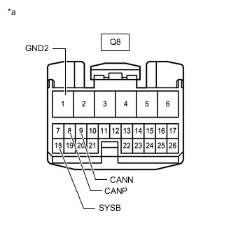
TELEMATICS TRANSCEIVER (w/ Telematics Transceiver)
Refer to Terminals of ECU.
-
Disconnect the cable from the negative (-) battery terminal.
-
Disconnect the telematics transceiver connector.
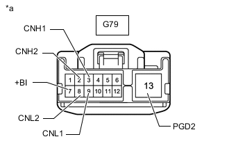
*a Front view of wire harness connector
(to Telematics Transceiver)
*b Front view of DLC3 -
Measure the resistance according to the value(s) in the table below.
-
-
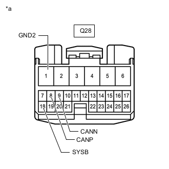
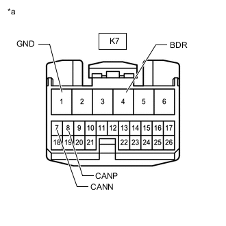
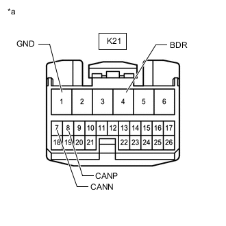
BUS BUFFER ECU (w/ Bus Buffer ECU)
-
Disconnect the bus buffer ECU connector.
*a Front view of wire harness connector
(to Bus Buffer ECU)
*b Front view of DLC3 -
Measure the resistance according to the value(s) in the table below.
-
-
ENGINE STOP AND START ECU (w/ Stop and Start System)
Refer to Terminals of ECU.
-
Disconnect the cable from the negative (-) battery terminal.
-
*a Front view of wire harness connector
(to Engine Stop and Start ECU)
Disconnect the engine stop and start ECU connectors.
-
Measure the resistance according to the value(s) in the table below.
-