FRONT ACCELERATION SENSOR REMOVAL
CAUTION / NOTICE / HINT
The necessary procedures (adjustment, calibration, initialization, or registration) that must be performed after parts are removed, installed, or replaced during the acceleration sensor removal/installation are shown below.
| Replacement Part or Procedure | Necessary Procedure | Effect/Inoperative when not Performed | Link |
|---|---|---|---|
| Disconnect cable from negative battery terminal | Drive the vehicle until stop and start control is permitted (approximately 5 to 60 minutes) | Stop and start system | |
| Memorize steering angle neutral point | LKA/LDA system | ||
| Parking support brake system* | |||
| Pre-collision system | |||
| Adaptive high beam system | |||
Lighting system (EXT) |
|||
| Variable gear ratio steering system | |||
| Parking assist monitor system | |||
| Panoramic view monitor system | |||
| Initialize rear door sunshade system | Rear door sunshade system | ||
| Initialize power trunk lid system | Power trunk lid system |
Click here Click here
Tech Tips
-
Use the same procedure for the RH and LH side.
-
The following procedure is for the LH side.
PROCEDURE
-
PRECAUTION
Note
After turning the engine switch off, waiting time may be required before disconnecting the cable from the negative (-) battery terminal. Therefore, make sure to read the disconnecting the cable from the negative (-) battery terminal notices before proceeding with work.
-
DISCONNECT CABLE FROM NEGATIVE BATTERY TERMINAL
Note
When disconnecting the cable, some systems need to be initialized after the cable is reconnected.
-
REMOVE FRONT DOOR SCUFF PLATE LH
-
REMOVE INSTRUMENT SIDE PANEL LH
-
REMOVE NO. 1 INSTRUMENT PANEL UNDER COVER SUB-ASSEMBLY
-
REMOVE COWL SIDE TRIM BOARD LH
-
REMOVE FRONT DOOR SCUFF PLATE RH
-
REMOVE INSTRUMENT SIDE PANEL RH
-
REMOVE NO. 2 INSTRUMENT PANEL UNDER COVER SUB-ASSEMBLY
-
REMOVE COWL SIDE TRIM BOARD RH
-
REMOVE ACCELERATION SENSOR ASSEMBLY
-
for LH Side:
-
Fold back the floor carpet.
-
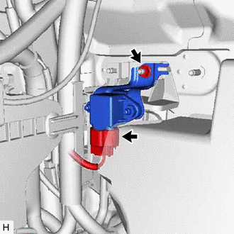
Remove the nut and acceleration sensor.
Note
-
Avoid any impact to the acceleration sensor.
-
Do not drop the acceleration sensor. If it is dropped, replace it with a new one.
-
-
Disconnect the connector from the acceleration sensor.
-
-
for RH Side:
-
Fold back the floor carpet.
-
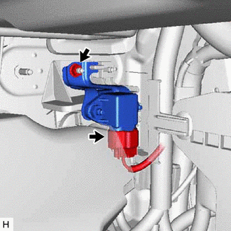
Remove the nut and acceleration sensor.
Note
-
Avoid any impact to the acceleration sensor.
-
Do not drop the acceleration sensor. If it is dropped, replace it with a new one.
-
-
Disconnect the connector from the acceleration sensor.
-
-