CYLINDER BLOCK DISASSEMBLY

CAUTION / NOTICE / HINT
The necessary procedures (adjustment, calibration, initialization, or registration) that must be performed after parts are removed and installed, or replaced during engine unit removal/installation are shown below.
| Replaced Part or Performed Procedure | Necessary Procedure | Effect/Inoperative Function when Necessary Procedure not Performed | Link | |
|---|---|---|---|---|
| Disconnect cable from negative battery terminal | Memorize steering angle neutral point | LKA/LDA System | ||
| Intelligent clearance sonar system*2 | ||||
| Pre-crash safety system | ||||
| Lighting system (EXT)
|
||||
| Adaptive high beam system | ||||
| Parking Assist Monitor System (w/ Parallel Parking Assist Function) | ||||
| Parking Assist Monitor System (w/o Parallel Parking Assist Function) | ||||
| Panoramic view monitor system | ||||
| Initialize back door lock | Power door lock control system | |||
| Reset back door close position | Power back door system | |||
| Replacement of ECM | Perform Vehicle Identification Number (VIN) or frame number registration |
|
for 2GR-FKS (w/ Canister Pump Module): for 2GR-FKS (w/o Canister Pump Module) |
|
| ECU Communication ID Registration (Immobiliser system) | Engine start function | See Service Bulletin for the registration method. | ||
| Perform code registration (Immobiliser system) |
|
|||
| Replacement of ECM (If possible, read the transaxle compensation code from the previous ECM) |
Possible to read transaxle compensation code | Perform the following procedures in the order shown:
|
|
Click here for Initialization (U881E) Click here for Registration (U881E) Click here for Initialization (U881F) Click here for Registration (U881F) |
| Impossible to read transaxle compensation code | Perform the following procedures in the order shown:
|
|||
w/ Canister Pump Module |
Inspection After Repair |
|
||
w/o Canister Pump Module |
Inspection After Repair |
|
||
| Replacement of automatic transaxle assembly | Perform the following procedures in the order shown:
|
|
for U881E Initialization: for U881E Registration: for U881F Initialization: for U881F Registration: |
|
| Front wheel alignment adjustment |
|
|
||
| Suspension, tires, etc. (The vehicle height changes because of suspension or tire replacement) |
|
|
||
| Rear television camera assembly optical axis (Back camera position setting) | Parking assist monitor system (w/ Parallel Parking Assist Function) | for Initialization: for Calibration: |
||
| Parking assist monitor system (w/o Parallel Parking Assist Function) | for Initialization: for Calibration: |
|||
|
Panoramic view monitor system | for Initialization: for Calibration: |
||
| Initialize headlight ECU sub-assembly LH |
|
|||
*2: When performing learning using the GTS.
Click here Click here
PROCEDURE
-
REMOVE CYLINDER BLOCK WATER JACKET SPACER
-
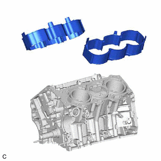
Remove the cylinder block water jacket spacer and cylinder block water jacket spacer LH from the cylinder block sub-assembly.
-
-
REMOVE PISTON SUB-ASSEMBLY WITH CONNECTING ROD
-
Check that the matchmarks on the connecting rod sub-assembly and connecting rod cap are aligned.
Tech Tips
The matchmarks on the connecting rod sub-assembly and connecting rod cap are guides for correct reassembly.
-
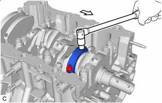

Front of Engine Remove the 2 connecting rod cap bolts.
-
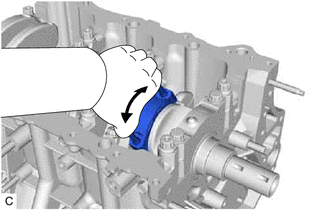
Using the 2 removed connecting rod cap bolts, remove the connecting rod cap and lower connecting rod bearing by wiggling the connecting rod cap right and left.
Tech Tips
Keep the lower connecting rod bearing installed to the connecting rod cap.
-
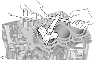
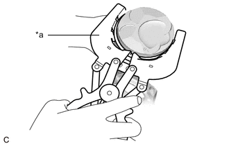
*a Ridge Reamer Using a ridge reamer, remove all of the carbon from the top of the cylinder.
-
Push the piston, connecting rod sub-assembly and upper connecting rod bearing through the top of the cylinder block sub-assembly.
Tech Tips
-
Keep the connecting rod bearing, connecting rod sub-assembly and connecting rod cap together.
-
Arrange the removed parts in such a way that they can be reinstalled to their original locations.
-
-
-
REMOVE CONNECTING ROD BEARING
-
Remove the connecting rod bearings from the connecting rod sub-assembly and connecting rod cap.
Tech Tips
Arrange the removed parts in such a way that they can be reinstalled to their original locations.
-
-
REMOVE PISTON RING SET
-
*a Piston Ring Expander Using a piston ring expander, remove the No. 1 compression ring and No. 2 compression ring.
-
Remove the oil ring expander and 2 side rails by hand.
Tech Tips
Arrange the removed parts in such a way that they can be reinstalled to their original locations.
-
-
REMOVE PISTON
-
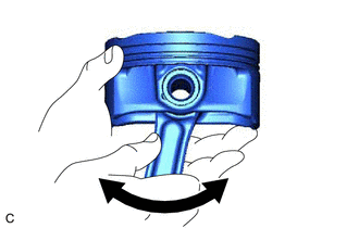
Check the fitting condition between the piston and piston pin.
-
Try to move the piston back and forth on the piston pin.
Tech Tips
If abnormal movement is felt, replace the piston and piston pin as a set.
-
-
Remove the connecting rod sub-assembly from the piston.
-
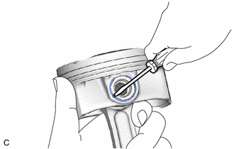
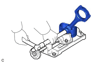
Using a screwdriver, pry out the piston pin hole snap ring (front side).
Note
-
Do not remove the piston pin hole snap ring (rear side) unless it has to be replaced.
-
Be careful not to damage the piston when removing the piston pin hole snap ring (rear side).
-
-
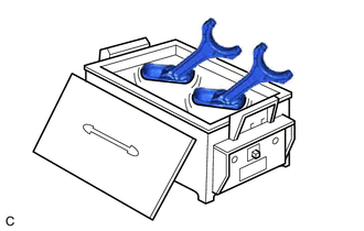
Gradually heat the piston to approximately 80°C (176°F).
CAUTION:
Be sure to wear protective gloves.
-
Using a brass bar and a hammer, lightly tap out the piston pin and remove the connecting rod sub-assembly.
Tech Tips
-
The piston and piston pin are a matched set.
-
Arrange the removed parts in such a way that they can be reinstalled to their original locations.
-
-
-
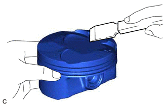
Using a gasket scraper, remove any carbon from the piston top.
Note
Be careful not to scratch the piston.
-
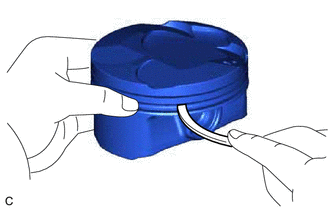
Using a groove cleaning tool or a broken ring, clean the piston ring grooves.
-
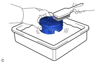
Using solvent and a brush, thoroughly clean the piston.
Note
Do not use a wire brush.
-
-
REMOVE CRANKSHAFT
-
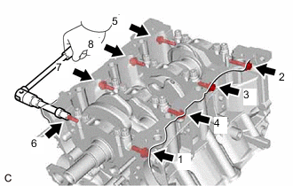
Uniformly loosen and remove the 8 crankshaft bearing cap set bolts and 8 seal washers in several steps in the order shown in the illustration.
-
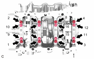
Uniformly loosen the 16 crankshaft bearing cap set bolts in several steps in the order shown in the illustration.
-
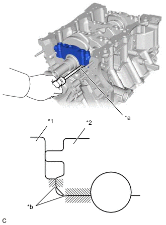
*1 Cylinder Block Sub-assembly *2 Crankshaft Bearing Cap *a Protective Tape *b Contact Surface Using a screwdriver with its tip wrapped with protective tape, pry out the crankshaft bearing caps. Remove the 4 crankshaft bearing caps and lower crankshaft bearings.
Note
-
Push up the crankshaft bearing cap slowly and evenly, alternating between the right and left side so that the crankshaft bearing cap can be removed.
-
Be careful not to damage the contact surfaces of the cylinder block sub-assembly and the crankshaft bearing cap.
-
-
Remove the crankshaft.
-
-
REMOVE CRANKSHAFT BEARING
-
Remove the upper crankshaft bearings and lower crankshaft bearings.
Tech Tips
Arrange the removed parts in such a way that they can be reinstalled to their original locations.
-
-
REMOVE CRANKSHAFT THRUST WASHER SET
-
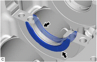
Remove the crankshaft thrust washer set from the cylinder block sub-assembly.
-
-
REMOVE NO. 1 OIL NOZZLE SUB-ASSEMBLY
-
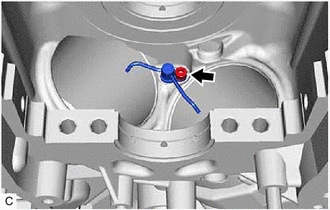
Using a 5 mm hexagon socket wrench, remove the 3 bolts and 3 No. 1 oil nozzle sub-assemblies.
-
Check the 3 No. 1 oil nozzle sub-assemblies for damage or clogging.
Tech Tips
If there is damage or clogs, replace the No. 1 oil nozzle sub-assembly.
-