BRAKE ACTUATOR(for RHD) INSTALLATION
PROCEDURE
-
INSTALL BRAKE ACTUATOR BRACKET CUSHION
-
Install the 3 brake actuator bolt cushions to the brake actuator bracket assembly.
-
-
INSTALL NO.1 BRAKE ACTUATOR CASE COLLAR
-
Install the 3 No. 1 brake actuator case collars to the brake actuator bracket cushions.
Note
Make sure the No. 1 brake actuator case collars are in full contact with the brake actuator bracket cushions.
-
-
INSTALL NO. 5 BRAKE ACTUATOR BRACKET
-
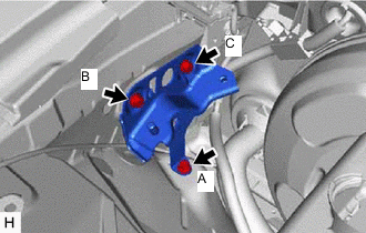
Install the No. 5 brake actuator bracket with the 3 bolts.
- Torque:
- 11 N*m { 112 kgf*cm, 8 ft.*lbf }
Note
-
Tighten the 3 bolts uniformly in alphabetical order.
-
Be careful not to damage the brake tubes.
-
-
INSTALL NO. 4 BRAKE ACTUATOR BRACKET
-
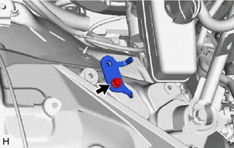
Install the No. 4 brake actuator bracket with the bolt.
- Torque:
- 11 N*m { 112 kgf*cm, 8 ft.*lbf }
Note
Be careful not to damage the brake tubes.
-
-
INSTALL BRAKE ACTUATOR BRACKET ASSEMBLY
-
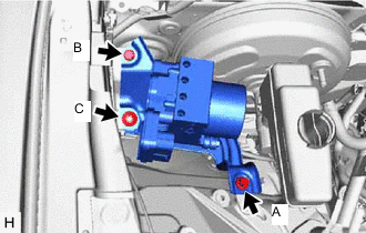
Install the brake actuator bracket assembly with the 3 bolts and nut.
- Torque:
- 5.4 N*m { 55 kgf*cm, 48 in.*lbf }
Note
Tighten the 3 bolts uniformly in alphabetical order.
-
-
INSTALL BRAKE ACTUATOR ASSEMBLY WITH BRACKET ASSEMBLY
-
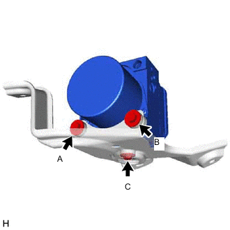
Install the brake actuator assembly with bracket with the 2 bolts and nut.
- Torque:
- 19 N*m { 194 kgf*cm, 14 ft.*lbf }
Note
-
Tighten the 2 bolts and nut uniformly in alphabetical order.
-
Be careful not to damage the brake tubes.
-
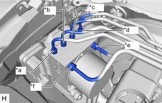
*a to Front Wheel Cylinder RH *b to Front Wheel Cylinder LH *c to Rear Wheel Cylinder RH *d to Rear Wheel Cylinder LH *e from Front Master Cylinder Port *f from Rear Master Cylinder Port Temporarily install each brake line to the correct positions of the brake actuator assembly with bracket as shown in the illustration.
-
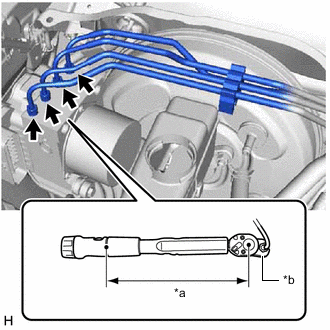
*a Torque Wrench Fulcrum Length *b Union Nut Wrench Using a union nut wrench, tighten each 4 brake lines.
- Torque:
- Specified tightening torque
- 15.2 N*m { 155 kgf*cm, 11 ft.*lbf }
Note
-
Do not kink or damage the brake lines.
-
Do not allow the brake lines to twist or interfere with other parts or the vehicle body during tightening.
-
Do not allow any foreign matter such as dirt or dust to enter the brake lines from the connecting parts.
Tech Tips
-
Calculate the torque wrench reading when changing the fulcrum length of the torque wrench.
-
When using a union nut wrench (fulcrum length of 22 mm (0.866 in.)) + torque wrench (fulcrum length of 162 mm (6.378 in.)): 13.4 N*m (137 kgf*cm, 10 ft.*lbf)
-
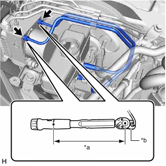
*a Torque Wrench Fulcrum Length *b Union Nut Wrench Using a union nut wrench, tighten each 2 brake lines.
- Torque:
- Specified tightening torque
- 19.5 N*m { 199 kgf*cm, 14 ft.*lbf }
Note
-
Do not kink or damage the brake lines.
-
Do not allow the brake lines to twist or interfere with other parts or the vehicle body during tightening.
-
Do not allow any foreign matter such as dirt or dust to enter the brake lines from the connecting parts.
Tech Tips
-
Calculate the torque wrench reading when changing the fulcrum length of the torque wrench.
-
When using a union nut wrench (fulcrum length of 20 mm (0.787 in.)) + torque wrench (fulcrum length of 162 mm (6.378 in.)): 17.4 N*m (177 kgf*cm, 13 ft.*lbf)
-
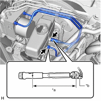
Connect the clamp and install the 2 brake lines.
-
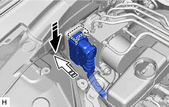

Lock Lever Locked 
Connector Connected Connect the wire harness connector to the brake actuator assembly, and then push up the lock lever to apply the lock.
Note
-
Before connecting the wire harness connector, make sure that the surfaces of the wire harness connector are free of foreign matter.
-
After connecting the wire harness connector, make sure that the lock lever is securely locked.
-
-
-
CONNECT UNION TO CHECK VALVE HOSE
-
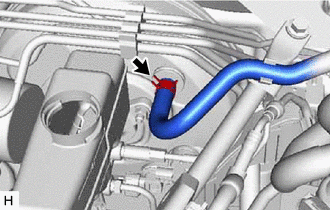
Slide the clip and connect the union to check valve hose to the brake booster assembly.
-
-
INSTALL COWL TOP VENTILATOR LOUVER SUB-ASSEMBLY
-
CONNECT CABLE TO NEGATIVE BATTERY TERMINAL
Note
When disconnecting the cable, some systems need to be initialized after the cable is reconnected.
-
BLEED BRAKE SYSTEM
-
PERFORM SYSTEM VARIANT LEARNING AND ACCELERATION SENSOR ZERO POINT CALIBRATION
-
INSPECT BRAKE ACTUATOR USING GTS
-
INSTALL FENDER APRON BRACE SUB-ASSEMBLY RH
-
INSTALL RADIATOR COVER PLATE