VEHICLE STABILITY CONTROL SYSTEM, Diagnostic DTC:C1241/41

| DTC Code | DTC Name |
|---|---|
| C1241/41 | Low Battery Positive Voltage or Abnormally High Battery Positive Voltage |
DESCRIPTION
If a malfunction is detected in the power supply circuit, the skid control ECU (housed in the brake actuator assembly) stores this DTC and the fail-safe function prohibits brake control system operation.
This DTC is stored when the IG1 terminal voltage deviates from the standard due to a malfunction in the power supply or charging circuit such as the battery, generator circuit, etc.
The DTC is cleared when the IG1 terminal voltage returns to normal.
| DTC Code | DTC Detection Condition | Trouble Area |
|---|---|---|
| C1241/41 | When any of the following is detected:
|
|
WIRING DIAGRAM
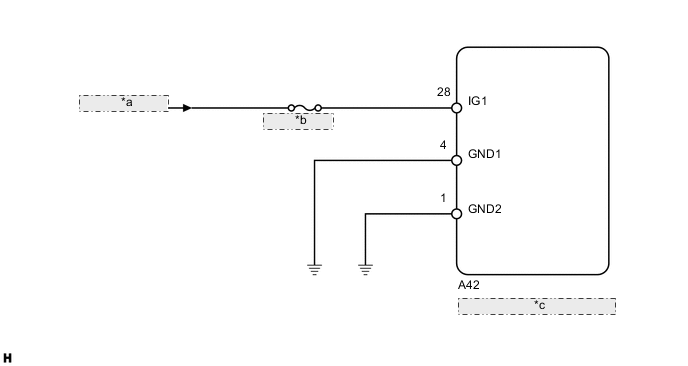
| *a | from IG Circuit |
| *b | ECU-IG NO. 1 |
| *c | Skid Control ECU (Brake Actuator Assembly) |
CAUTION / NOTICE / HINT
Note
-
When replacing the skid control ECU (brake actuator assembly), perform the engine variant learning Click here.
-
Inspect the fuses for circuits related to this system before performing the following inspection procedure.
PROCEDURE
-
CHECK HARNESS AND CONNECTOR (IG1 TERMINAL)
-
Turn the ignition switch off.
-
Disconnect the skid control ECU connector.
-
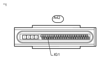
Text in Illustration *1 Front view of wire harness connector
(to Skid Control ECU)
Measure the voltage according to the value(s) in the table below.
Standard Voltage Tester Connection Switch Condition Specified Condition A42-28 (IG1) - Body ground Ignition switch ON 11 to 14 V
NG 
REPAIR OR REPLACE HARNESS OR CONNECTOR
OK 
-
-
CHECK HARNESS AND CONNECTOR (GND1, GND2 TERMINAL)
-
Turn the ignition switch off.
-
Disconnect the skid control ECU connector.
-
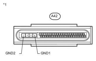
Text in Illustration *1 Front view of wire harness connector
(to Skid Control ECU)
Measure the resistance according to the value(s) in the table below.
Standard Resistance Tester Connection Condition Specified Condition A42-4 (GND1) - Body ground Always Below 1 Ω A42-1 (GND2) - Body ground Always Below 1 Ω
NG
REPAIR OR REPLACE HARNESS OR CONNECTOR
OK
-
-
RECONFIRM DTC
-
Clear the DTCs Click here.
-
Start the engine.
-
Perform a road test.
-
Check if the same DTC is output Click here.
Result Result Proceed to DTC C1241/41 is not output. A DTC C1241/41 is output. B
A
USE SIMULATION METHOD TO CHECK Click here
B
REPLACE BRAKE ACTUATOR ASSEMBLY Click here
-