FC STACK REMOVAL

CAUTION / NOTICE / HINT
The necessary procedures (adjustment, calibration, initialization, or registration) that must be performed after parts are removed, installed, or replaced during the FC stack assembly removal/installation are shown below.
| Replacement Part or Procedure | Necessary Procedure | Effect/Inoperative when not Performed | Link |
|---|---|---|---|
| Replace FC stack assembly | Perform the utility "FC Stack Shock History Clear" | Because the displayed value of Data List item "FC Stack Shock History" has not been cleared, when future on-vehicle inspections of the FC stack assembly are performed, a correct judgment cannot be made. |
CAUTION:
-
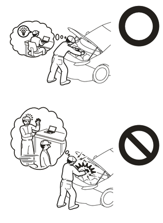
This vehicle contains high voltage circuits standardized with orange colored wiring and connectors, so follow the instructions in this manual to perform the procedures correctly.
-
If the correct procedures are not followed according to the instructions in this manual, there is a danger of electric shock from the high voltage circuits.
-
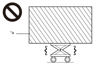
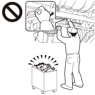
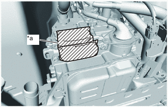
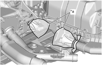
*a Heavy object exceeding the capacity of the engine lifter Because the weight of the FC stack with FC converter assembly is extremely heavy, make sure to follow the work procedures described in the repair manual.
-
If work is not performed according to the procedures described in the repair manual, there is a danger that the engine lifter could drop and components could fall down.
-
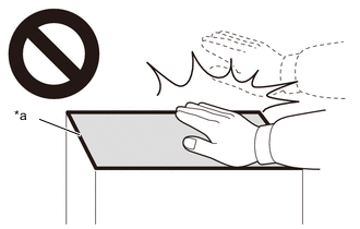
*a High temperature areas Do not touch the FC stack assembly or its surroundings when they are hot.
-
Touching the FC stack assembly or its surroundings when they are hot could result in burns.
-

Be sure to wear insulating gloves when working on high voltage wiring or components.
-
If work is performed without wearing insulating gloves, there is a danger of electric shock.
Note
When the vehicle is parked with the power switch off, if the FC control ECU judges that the FC stack temperature will go below 0°C (32°F), it activates the FC air compressor, hydrogen pump and FC cooling water pump for a maximum of 180 seconds and drains water from the FC stack assembly. When performing inspection or repairs with the power switch off (not on (IG) or on (READY)), disconnect the cable from the negative (-) auxiliary battery terminal before performing work.
PROCEDURE
-
CAUTIONS FOR HIGH VOLTAGE SYSTEM COMPONENTS
Note
-
Do not allow foreign matter to enter the opening of the connector.
-
Do not touch the connector terminals.
-
Do not turn the power switch on (READY) before filling the coolant (for inverter).
-
When turning power switch on (IG), do not also turn the power switch on (READY).
-
Do not attempt to repair the connector terminal or the threads of the aluminum case.
-
Be careful not to drop parts, damage parts with tools, or allow interference or impacts with surrounding components.
-
Do not apply excessive force to the wire harnesses.
-
Do not apply oil or grease to the bolts.
-
-
CAUTIONS FOR COMPRESSED HYDROGEN GAS
-
CAUTIONS FOR COOLANT (FC STACK COOLANT)
-
REMOVE FRONT BUMPER LOWER ABSORBER
-
REMOVE NO. 3 RADIATOR AIR GUIDE
-
REMOVE NO. 2 MOTOR UNDER COVER
-
REMOVE FRONT FLOOR COVER LH
-
REMOVE FRONT FLOOR COVER RH
-
REMOVE SUSPENSION MEMBER TO FRONT CROSSMEMBER BRACE SUB-ASSEMBLY
-
REMOVE FRONT FLOOR CENTER COVER LH
-
REMOVE FRONT FLOOR CENTER COVER RH
-
REMOVE NO. 2 FLOOR UNDER COVER
-
REMOVE NO. 1 FLOOR UNDER COVER
-
PRESSURE RELEASE OPERATION
-
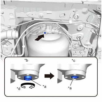
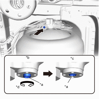
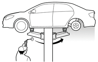
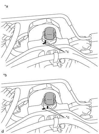
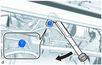
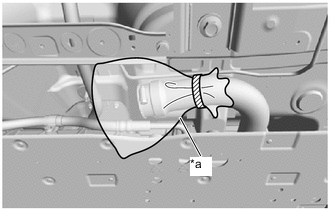
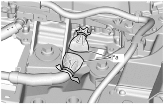
*a Adjustment Bolt *b Manual Valve Open *c Manual Valve Closed *d Clockwise Using an 8 mm hexagon socket wrench, rotate the adjustment bolt clockwise to close the manual valve of the No. 1 hydrogen tank assembly.
- Torque:
- 20 N*m { 204 kgf*cm, 15 ft.*lbf }
Note
-
The manual valve shuts off the pressure from the hydrogen tank assembly, so be careful not to damage the hexagonal portion.
-
If the hexagonal portion has been damaged, the No. 1 hydrogen tank assembly must be replaced.
-
*a Adjustment Bolt *b Manual Valve Open *c Manual Valve Closed *d Clockwise Using an 8 mm hexagon socket wrench, rotate the adjustment bolt clockwise to close the manual valve of the No. 2 hydrogen tank assembly.
- Torque:
- 20 N*m { 204 kgf*cm, 15 ft.*lbf }
Note
-
The manual valve shuts off the pressure from the hydrogen tank assembly, so be careful not to damage the hexagonal portion.
-
If the hexagonal portion has been damaged, the No. 1 hydrogen tank assembly must be replaced.
-
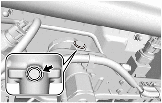
Before starting the depressurization procedure, first check that there is no mud or other contaminant around the medium pressure leak check port of the hydrogen supply regulator assembly, and clean it as necessary.
Tech Tips
Installing the No. 1 hydrogen supply regulator plug while any foreign matter adheres to it can cause a hydrogen gas leak.
-
Perform the depressurization procedure.
-
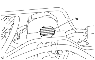
Make sure that the manual valves of the No. 1 hydrogen tank assembly and No. 2 hydrogen tank assembly are closed.
-
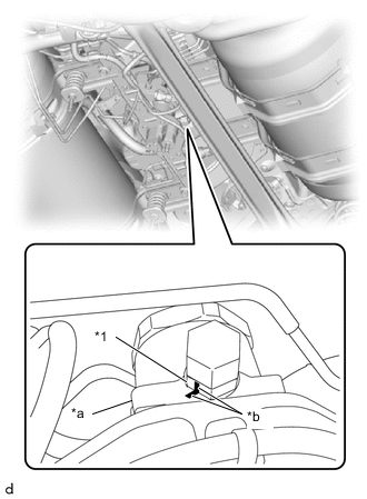
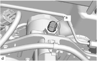
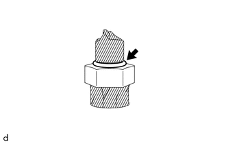
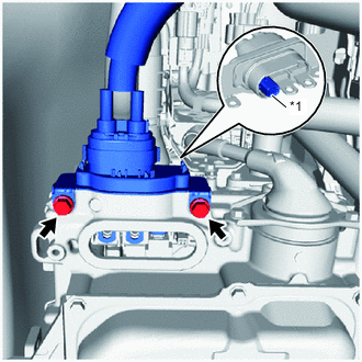
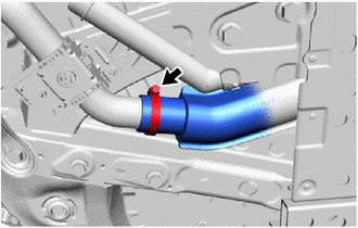
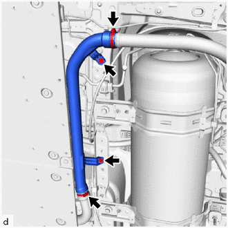
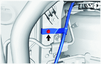
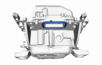
*1 Hydrogen Supply Regulator Union *a Body *b Paint Mark Apply paint marks to the hydrogen supply regulator union and the body of the hydrogen supply regulator assembly as shown in the illustration.
Tech Tips
When loosening the No. 1 hydrogen supply regulator plug, there is a possibility that the hydrogen supply regulator union could turn together with it and be loosened, so applying paint marks will enable judgment of whether the hydrogen supply regulator union has been loosened.
-
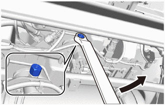
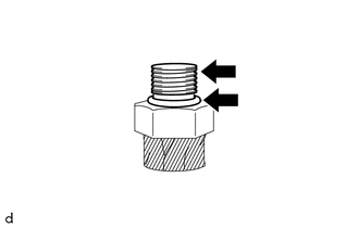
Slowly loosen the No. 1 hydrogen supply regulator plug until the hissing sound of gas escaping can be heard, then stop loosening the No. 1 hydrogen supply regulator plug and wait for the sound to stop. Repeat this procedure multiple times until the sound stops occurring, in order to depressurize the compressed hydrogen gas from the medium pressure leak check port of the hydrogen supply regulator assembly.
CAUTION:
-
Do not perform depressurization procedures when the manual valve of the hydrogen tank assembly is open.
-
The highly pressurized hydrogen gas inside the hydrogen tank assembly could blow out, resulting in a serious accident.
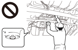
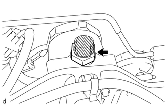
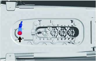
*a Manual Valve Open
-
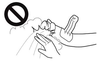
When performing depressurization, do not perform procedures by hand without wearing protective glasses and gloves.
-
High pressure nitrogen gas could cause a serious accident.
Note
When performing depressurization, only loosen the No. 1 hydrogen supply regulator plug. Do not remove it.
-
-
-
Blow compressed air around the underside of the vehicle.
-
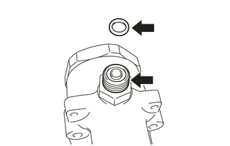
Remove the No. 1 hydrogen supply regulator plug from the hydrogen supply regulator union.
Note
When frost has formed on the hydrogen tank assembly or piping, water droplets may be formed when the frost begins to melt. If water droplets enter the tank or piping, it could result in blockage of the hydrogen piping, so do not allow water droplets to enter the tank or piping.
-
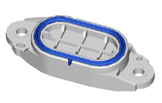
Remove the O-ring from the hydrogen supply regulator union.
-
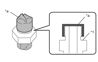
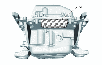
*a Protective Tape To prevent damage to the seal portions and threaded portions, and to prevent foreign matter such as dust or metal fragments from entering the openings, cover the seal portions, threaded portions, and openings of the hydrogen supply regulator union with protective tape.
-
*a Correct *b Incorrect *c Paint Mark Check that the hydrogen supply regulator union has not been loosened.
Tech Tips
If the hydrogen supply regulator union has been loosened, there is the possibility of a compressed hydrogen gas leak, so it is necessary to remove the hydrogen supply regulator union and replace the O-ring with a new one.
-
Procedures for when the hydrogen supply regulator union has been loosened:
-
Remove the hydrogen supply regulator union.
Note
When frost has formed on the hydrogen tank assembly or piping, water droplets may be formed when the frost begins to melt. If water droplets enter the tank or piping, it could result in blockage of the hydrogen piping, so do not allow water droplets to enter the tank or piping.
-
*a Protective Tape To prevent foreign matter such as dust or metal fragments from entering the openings, cover the seal portions, threaded portions, and openings of the hydrogen supply regulator union installation portion with protective tape.
-
Remove the O-ring from the hydrogen supply regulator union.
Note
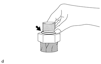
Perform the procedure by hand. Do not use any tools.
-
Clean and degrease the threaded portion of the hydrogen supply regulator union.
-
*1 Hydrogen Supply Regulator Union *a Protective Tape To prevent the O-ring from being damaged during installation, apply protective tape as shown in the illustration.
Tech Tips
Cover the hydrogen supply regulator union with protective tape so that the threaded portion and the hole cannot be seen.
-
Coat a new O-ring with TOYOTA Genuine FC Grease.
-
Install the O-ring to the hydrogen supply regulator union.
Note
-
Make sure not to damage the O-ring.
-
Make sure the O-ring is not twisted.
-
-
Remove the protective tape from the hydrogen supply regulator union.
Note
When frost has formed on the hydrogen tank assembly or piping, water droplets may be formed when the frost begins to melt. If water droplets enter the tank or piping, it could result in blockage of the hydrogen piping, so do not allow water droplets to enter the tank or piping.
-
Coat the O-ring and the threaded portion of the hydrogen supply regulator union with TOYOTA Genuine FC Grease.
-
To prevent the hydrogen supply regulator union installation portion from being contaminated by dust, metal fragments, etc., do not remove the protective tape from it until immediately before performing the work.
Note
When frost has formed on the hydrogen tank assembly or piping, water droplets may be formed when the frost begins to melt. If water droplets enter the tank or piping, it could result in blockage of the hydrogen piping, so do not allow water droplets to enter the tank or piping.
-
Install the hydrogen supply regulator union.
- Torque:
- 41.5 N*m { 423 kgf*cm, 31 ft.*lbf }
Note
When installing the O-ring, make sure that it is not pinched.
-
-
To prevent damage to the seal portions and threaded portions, and to prevent foreign matter such as dust or metal fragments from entering the openings, do not remove the protective tape covering the seal portions, threaded portions, and openings of the hydrogen supply regulator union until immediately before performing work.
Note
When frost has formed on the hydrogen tank assembly or piping, water droplets may be formed when the frost begins to melt. If water droplets enter the tank or piping, it could result in blockage of the hydrogen piping, so do not allow water droplets to enter the tank or piping.
-
Apply TOYOTA Genuine FC Grease to a new O-ring and to the threaded portion of the hydrogen supply regulator union.
-
Install the O-ring to the hydrogen supply regulator union.
Note
During installation, make sure not to damage the O-ring.
-
Install the No. 1 hydrogen supply regulator plug to the hydrogen supply regulator union.
- Torque:
- 25 N*m { 255 kgf*cm, 18 ft.*lbf }
-
-
REMOVE SERVICE PLUG GRIP (for EV)
-
REMOVE FC STACK SERVICE PLUG GRIP
-
SEPARATE WIRE HARNESS
-
Remove the bolt to separate the wire harness from the vehicle.
-
-
REMOVE INVERTER COVER
-
REMOVE INVERTER TERMINAL COVER
-
CHECK TERMINAL VOLTAGE
CAUTION:
Wear insulated gloves.
Note
Do not allow foreign matter or water droplets to enter the inverter with converter assembly.
-
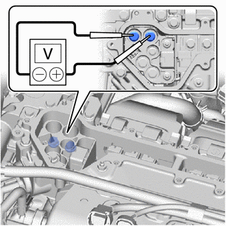
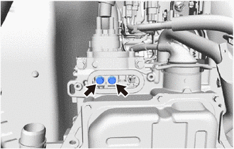
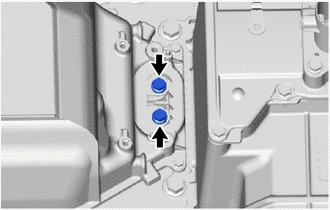
Using a voltmeter, measure the voltage between the 2 terminals.
Standard Voltage 0 V Tech Tips
Use a measuring range of DC 750 V or more on the voltmeter.
-
-
INSTALL INVERTER TERMINAL COVER
CAUTION:
Wear insulated gloves.
Note
To prevent foreign matter or water droplets from entering the inverter with converter assembly, install the inverter terminal cover after "CHECK TERMINAL VOLTAGE".
-
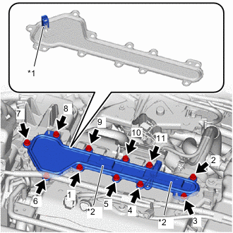
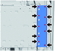
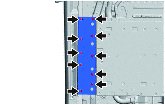
*1 Interlock Connector *2 Connector Bracket Temporarily install the inverter terminal cover to the inverter with converter assembly with the 11 bolts.
Note
-
Check that the rubber seal is installed to the inverter terminal cover, and install the inverter terminal cover to the inverter with converter assembly.
-
Do not touch the rubber seal of the inverter terminal cover.
-
Do not install the inverter terminal cover while pressing down on the connector bracket.
-
Securely connect the interlock connector.
-
-
Tighten the 11 bolts in the order shown in the illustration.
- Torque:
- 8.0 N*m { 82 kgf*cm, 71 in.*lbf }
-
Engage the 2 clamps to connect the wire harness to the inverter terminal cover.
-
Connect the 4 connectors.
-
-
DRAIN COOLANT (FC STACK COOLANT)
-
DRAIN COOLANT (for Inverter)
-
DISCONNECT FC CONVERTER POWER OUTLET CABLE
CAUTION:
Wear insulated gloves.
-
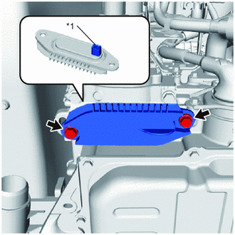
*1 Interlock Connector Remove the 2 bolts and front FC converter service hole cover from the FC converter assembly.
Note
-
The front FC converter service hole cover has an interlock connector, so pull it down straight.
-
Make sure not to drop the gasket of the front FC converter service hole cover.
-
-
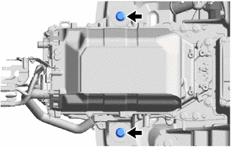
Using an insulated tool, remove the 2 bolts.
-
*1 Interlock Connector Using an insulated tool, remove the 2 bolts and disconnect FC converter power outlet cable from the FC converter assembly.
Note
-
The FC converter power outlet cable has an interlock connector, so pull it out straight.
-
Do not touch the rubber seal or terminal portion of the FC converter power outlet cable.
-
Do not apply any impacts to the terminal portion of the FC converter power outlet cable.
-
Do not scratch or damage the FC converter assembly with the terminal portion of the FC converter power outlet cable.
-
Insulate the terminal portion of the FC converter power outlet cable by wrapping it with insulating tape.
-
-
*a Protective Tape To prevent contamination by foreign matter or water droplets, cover the openings of the FC converter assembly with protective tape.
-
-
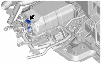
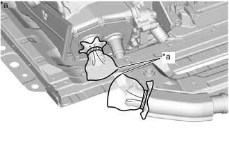
DISCONNECT NO. 2 INVERTER COOLING OUTLET HOSE
-
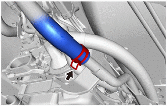
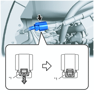
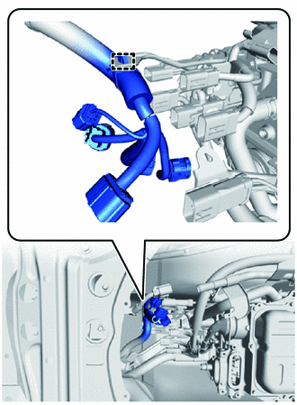
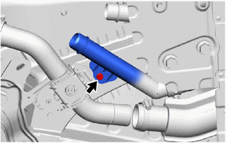
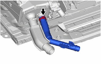
Slide the hose clip and disconnect the No. 2 inverter cooling outlet hose from the FC converter cooling water inlet pipe.
Note
Disconnect slowly to prevent coolant (for inverter) from splattering.
-
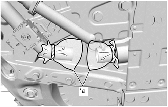
*a Plastic Bag To prevent contamination by foreign matter, cover the connecting portions of the No. 2 inverter cooling outlet hose and FC converter cooling water inlet pipe with plastic bags.
-
-
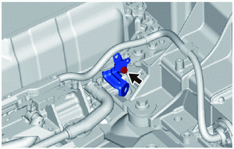
DISCONNECT NO. 2 EV WATER HOSE CONNECTOR
-
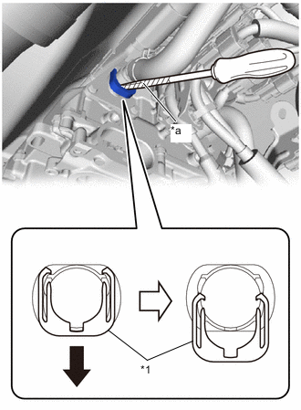
*1 Retainer *a Protective Tape 
Press Down Disconnect the No. 2 EV water hose connector.
Note
Before disconnecting the No. 2 EV water hose connector, check that there is no mud or other contaminant on the connecting portions of the No. 2 EV water hose connector and FC converter assembly, and clean away any contaminants.
-
Using a screwdriver with its tip wrapped in protective tape, press down the retainer of the No. 2 EV water hose connector to release the lock.
-
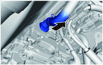
Disconnect Slowly Disconnect the No. 2 EV water hose connector, together with the FC converter cooling water outlet hose, from the FC converter assembly.
Note
-
Perform the procedures by hand. Do not use any tools.
-
Do not forcefully bend, fold, or twist the No. 2 EV water hose connector and FC converter cooling water outlet hose.
-
Disconnect slowly to prevent coolant (for inverter) from splattering.
-
If the 2 O-rings on the inner side of the No. 2 EV water hose connector are damaged or falling out, replace the No. 2 EV water hose connector with a new one.
-
-
After disconnecting the No. 2 EV water hose connector, check that there is no mud or other contaminant on the connecting portions of the FC converter assembly, and clean away any contaminants.
-
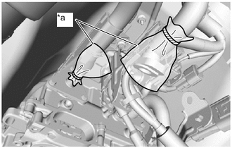
*a Plastic Bag To prevent contamination by foreign matter, cover the connecting portions of the No. 2 EV water hose connector and FC converter assembly with plastic bags.
-
-
-
SEPARATE WIRE HARNESS
CAUTION:
Wear insulated gloves.
-
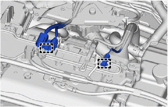
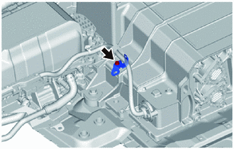
*1 Green-colored Lock Pull out the green lock of the connector and disengage the connector as shown in the illustration.
Note
-
Do not touch the connector terminals.
-
Insulate the opening of the connector by wrapping it with insulating tape.
-
-
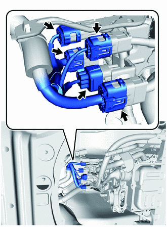
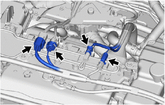
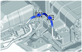
Disconnect the 5 connectors.
Note
Do not touch the connector terminals.
-
Disengage the clamp to separate the wire harness from the wire harness clamp bracket.
Note
When disengaging the clamp, be careful not to damage the clamp.
-
-
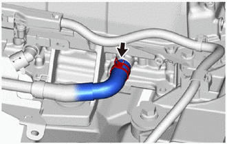
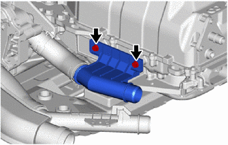
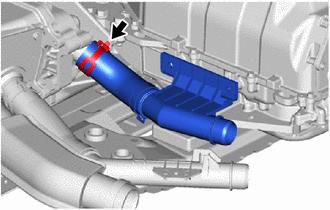
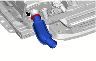
DISCONNECT FC STACK AIR INLET HOSE
-
Loosen the hose clamp and disconnect the FC stack air inlet hose from the No. 2 FC air compressor outlet pipe.
-
*a Plastic Bag To prevent contamination by foreign matter or water droplets, cover the connecting portions of the FC stack air inlet hose and No. 2 FC air compressor outlet pipe with plastic bags.
-
-
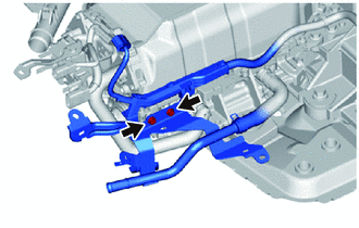
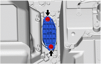
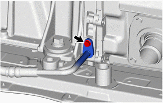
SEPARATE FC STACK COOLING WATER OUTLET PIPE
-
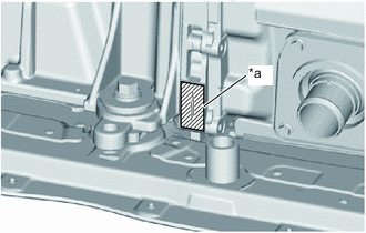
Remove the bolt and separate the FC stack cooling water outlet pipe from the vehicle.
-
-
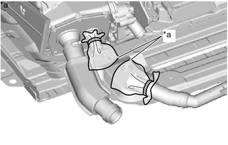
REMOVE NO. 2 FC EXHAUST PIPE
-
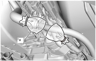
Loosen the 2 clamps.
-
Remove the 2 bolts and No. 2 FC exhaust pipe from the No. 1 FC exhaust pipe, No. 3 FC exhaust pipe and vehicle body.
CAUTION:
-
If the water remaining inside the No. 2 FC exhaust pipe is hot, do not touch the water directly.
-
Touching the water remaining inside the No. 2 FC exhaust pipe when it is hot could result in burns.
Note
-
If there are any scratches or other damage on the inner surface or insertion portions of the No. 2 FC exhaust pipe, or on the insertion portions of the No. 1 FC exhaust pipe or No. 3 FC exhaust pipe, replace the damaged part with a new one.
-
If the clamp is damaged or rusty, replace it with a new one.
-
-
*a Plastic Bag To prevent contamination by foreign matter, cover the connecting portion of the No. 1 FC exhaust pipe with a plastic bag.
-
-
SEPARATE NO. 3 PARKING BRAKE CABLE ASSEMBLY
-
Remove the bolt to separate the No. 3 parking brake cable assembly from the vehicle.
-
-
SEPARATE NO. 2 HYDROGEN SUPPLY TUBE SUB-ASSEMBLY
-
DISCONNECT NO. 1 HYDROGEN SUPPLY TUBE SUB-ASSEMBLY
-
REMOVE FRAME REAR CROSSMEMBER EXTENSION LH
-
Remove the 10 bolts and frame rear crossmember extension LH from the vehicle.
Note
Be careful of the brake tube when removing.
-
-
REMOVE FRAME REAR CROSSMEMBER EXTENSION RH
-
Remove the 10 bolts and frame rear crossmember extension RH from the vehicle.
-
-
REMOVE REAR FRAME ASSEMBLY
-
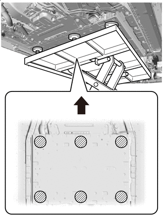
Front Side of Vehicle 
Attachment installation position Using a height adjustment attachment, set the engine lifter, together with the FC stack with FC converter assembly, to the rear frame assembly.
Note
Set so that the rear frame assembly is horizontal and level.
-
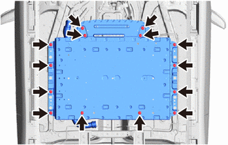
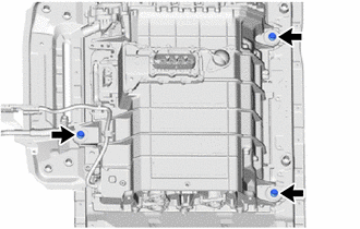
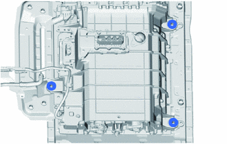
Remove the 14 bolts, and remove the rear frame assembly, together with the FC stack with FC converter assembly, from the vehicle.
Note
Be careful of the wire harnesses and hoses when removing.
-
-
SEPARATE WIRE HARNESS
CAUTION:
Wear insulated gloves.
-
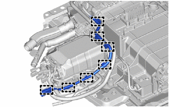
Disengage the 7 clamps to separate the wire harness and connector from the FC converter assembly and FC stack assembly.
Note
When disengaging the clamps, be careful not to damage the clamps.
-
Remove the 3 bolts to separate the 3 wire harness clamp brackets from the FC converter assembly and FC stack assembly.
Note
Do not disengage the clamps before removing the wire harness clamp brackets.
-
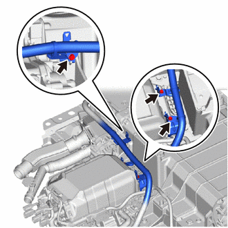
*1 Grommet Disengage the 7 clamps to separate the wire harness from the wire harness clamp bracket.
Note
-
When disengaging the clamps, be careful not to damage the clamps.
-
Do not remove the grommet.
-
-
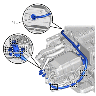
Disconnect the connector.
-
Remove the 2 bolts to separate the FC converter cooling water inlet pipe, together with the wire harness, from the FC converter assembly.
Note
To avoid possibly damaging the clamp, do not disengage the wire harness clamp and FC converter cooling water inlet pipe when not replacing the FC stack assembly.
-
Remove the bolt and wire harness clamp bracket from the FC converter assembly.
-
Slide the hose clip and disconnect the FC converter cooling water inlet hose from the FC converter assembly.
-
*a Plastic Bag To prevent contamination by foreign matter, cover the connecting portions of the FC converter cooling water inlet hose and FC converter assembly with plastic bags.
-
Disengage the 2 clamps to separate the wire harness from the wire harness clamp bracket.
Note
When disengaging the clamps, be careful not to damage the clamps.
-
-
REMOVE WIRE HARNESS CLAMP BRACKET
-
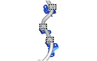
Disengage the 3 clamps to remove the 3 wire harness clamp brackets from the wire harness.
Note
When disengaging the clamps, be careful not to damage the clamps.
-
Remove the bolt and wire harness clamp bracket from the FC stack assembly.
-
-
SEPARATE FC STACK COOLING WATER INLET PIPE
-
Remove the 2 bolts to separate the FC stack cooling water inlet pipe from the FC converter assembly.
-
-
REMOVE FC STACK COOLING WATER INLET HOSE
-
Slide the hose clip and remove the FC stack cooling water inlet hose from the FC stack assembly.
-
*a Plastic Bag To prevent contamination by foreign matter, cover the connecting portions of the FC stack cooling water inlet hose and FC stack assembly with plastic bags.
-
-
REMOVE FC CONVERTER ASSEMBLY
CAUTION:
Wear insulated gloves.
-
To prevent contamination by foreign matter or water droplets, check that the area around the rear FC converter service hole cover has no foreign matter or water droplets, and clean away any foreign matter or water droplets found.
Note
Do not allow foreign matter or water droplets to enter any other components.
-
Remove the 2 bolts and rear FC converter service hole cover from the FC converter assembly.
Note
Be careful that foreign matter or water droplets do not enter the FC converter assembly.
-
Remove the rear FC converter service hole gasket from the rear FC converter service hole cover.
Note
Perform the procedures by hand. Do not use any tools.
-
Using an insulated tool, remove the 2 bolts.
Note
Be careful that foreign matter or water droplets do not enter the FC converter assembly.
-
*a Protective Tape To prevent contamination by foreign matter or water droplets, cover the opening of the FC converter assembly with protective tape.
-
Remove the 2 bolts.
-
Remove the 2 No. 2 FC stack mounts from the FC converter assembly.
-
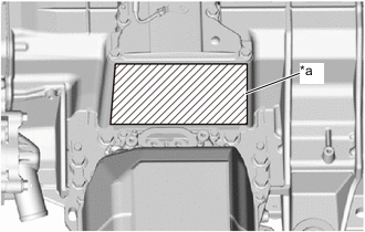
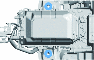
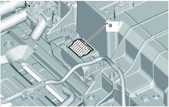
*a Protective Tape To avoid damaging the No. 1 FC stack caution label, protect the No. 1 FC stack caution label using protective tape or similar.
Tech Tips
This procedure is only performed when the FC stack assembly is not being replaced with a new one.
-
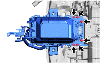
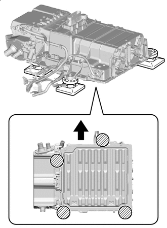
Remove the 6 bolts and FC converter assembly from the FC stack assembly.
Note
-
Do not hold the FC converter assembly by its pipe portion.
-
Be careful that foreign matter or water droplets do not enter the FC stack assembly and FC converter assembly.
-
If the FC converter assembly has been dropped, damaged or subjected to a strong impact, replace it with a new one.
-
-
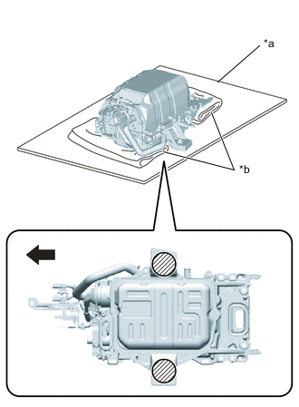
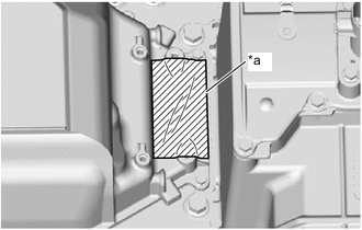
*a Cardboard *b Cloth Front Side of Vehicle Grounding Location Ground the FC converter assembly in the location indicated by the illustration, and place the FC converter assembly on a piece of cardboard.
Note
-
Do not place the bottom side of the FC converter assembly directly on the floor.
-
Do not place the FC converter assembly upside-down.
-
To avoid damaging or deforming the FC converter assembly, do not ground the FC converter assembly in a location other than the one shown in the illustration.
-
Set so that the FC converter assembly is horizontal and level.
-
To avoid damaging or deforming the FC converter assembly, place a piece of cloth or similar in the location shown in the illustration.
-
-
*a Protective Tape To prevent contamination by foreign matter or water droplets, cover the opening of the FC stack assembly with protective tape.
-
Remove the rear FC converter gasket from the FC converter assembly.
Note
Perform the procedures by hand. Do not use any tools.
-
*a Protective Tape To prevent contamination by foreign matter or water droplets, cover the opening of the FC converter assembly with protective tape.
-
-
REMOVE FC STACK COOLING WATER OUTLET HOSE
-
Slide the hose clip and remove the FC stack cooling water outlet hose from the FC stack assembly.
-
*a Plastic Bag To prevent contamination by foreign matter, cover the connecting portions of the FC stack cooling water outlet hose and FC stack assembly with plastic bags.
-
-
REMOVE FC STACK AIR INLET HOSE
-
Loosen the hose clamp and remove the FC stack air inlet hose from the FC stack assembly.
-
*a Plastic Bag To prevent contamination by foreign matter or water droplets, cover the connecting portions of the FC stack air inlet hose and FC stack assembly with plastic bags.
-
-
REMOVE NO. 1 FC EXHAUST PIPE
-
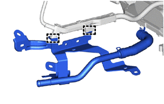
REMOVE NO. 1 HYDROGEN SUPPLY TUBE SUB-ASSEMBLY
-
Remove the bolt and disconnect the No. 1 hydrogen supply tube sub-assembly from the FC stack assembly.
-
*a Protective Tape To prevent contamination by foreign matter or water droplets, cover the connecting portion of the FC stack assembly with protective tape.
-
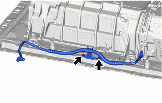
Remove the 2 bolts and No. 1 hydrogen supply tube sub-assembly from the rear frame assembly.
-
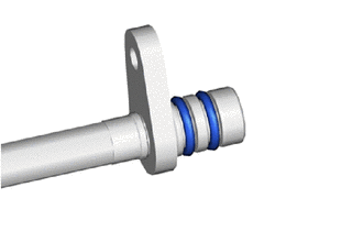
Remove the 2 O-rings from the No. 1 hydrogen supply tube sub-assembly.
-
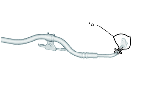
*a Plastic Bag To prevent contamination by foreign matter or water droplets, cover the No. 1 hydrogen supply tube sub-assembly with a plastic bag.
-
-
REMOVE FC STACK ASSEMBLY
CAUTION:
Wear insulated gloves.
-
Remove the 3 bolts.
-
Remove the 3 No. 2 FC stack mounts from the FC stack assembly.
-
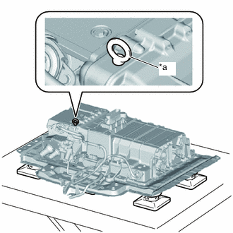
*a Eye Bolt Install an eye bolt in the location shown in the illustration.
Tech Tips
Eye Bolt Installation Hole SizeNominal Diameter [mm] Pitch [mm] Depth [mm] M10 1.5 18 -
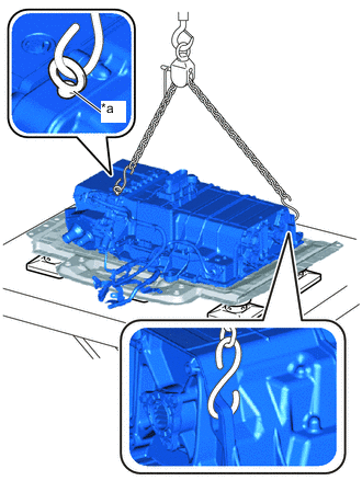
*a Eye Bolt Using an engine sling device, set it in the location shown in the illustration, and remove the FC stack assembly from the rear frame assembly.
Note
-
Do not hoist the FC stack assembly from locations other than those shown in the illustration.
-
Make sure that wire harnesses are not caught when hoisting.
-
To avoid damaging or deforming the FC stack assembly, be careful of the hoisting angle of the engine sling device.
-
Set the engine sling device so that the FC stack assembly is horizontal and level.
-
-
Front Side of Vehicle Attachment installation position Using the height adjustment attachment, set it so that it contacts the FC stack assembly in the location shown in the illustration, and set the FC stack assembly on the height adjustment attachment.
Note
-
To avoid damaging or deforming the FC stack assembly, do not attach the height adjustment attachment to the plastic portions or to the lower cover on the bottom surface of the FC stack assembly.
-
Set so that the FC stack assembly is horizontal and level.
-
Do not place the bottom side of the FC stack assembly directly on the floor.

*a Plastic Portions *b Lower Cover -
-
Remove the eye bolt.
-
-
REMOVE FC CONVERTER COOLING WATER INLET PIPE
Tech Tips
This procedure is only performed when the FC stack assembly is being replaced with a new one.
-
Disengage the 2 clamps to remove the FC converter cooling water inlet pipe from the wire harness.
Note
To avoid possibly damaging the clamp, do not disengage the wire harness clamp and FC converter cooling water inlet pipe when not replacing the FC stack assembly.
-