REAR CRANKSHAFT OIL SEAL INSTALLATION

Note
for Manual Transaxle:
When the transaxle is removed, be sure to use a new clutch release with bearing cylinder and new installation bolts. Removal of the transaxle allows the compressed clutch release with bearing cylinder to return to its original position, and dust could damage the seal of the clutch release with bearing cylinder, possibly causing clutch fluid leaks.
-
INSTALL ENGINE REAR OIL SEAL
-
Apply MP grease to the lip of a new oil seal.
Note
-
Do not allow foreign matter to contact the lip of the oil seal.
-
Do not allow MP grease to contact the dust seal.
-
-
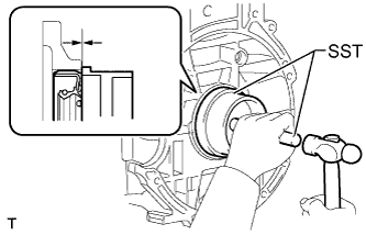
Using SST and a hammer, tap in the oil seal until its surface is flush with the edges of the cylinder block and crankcase.
- SST
- 09223-15030
- 09950-70010 ( 09951-07100 )
Note
-
Wipe off any extra grease from the crankshaft.
-
Do not tap in the oil seal at an angle.
-
-
INSTALL DRIVE PLATE AND RING GEAR SUB-ASSEMBLY (for CVT)
-
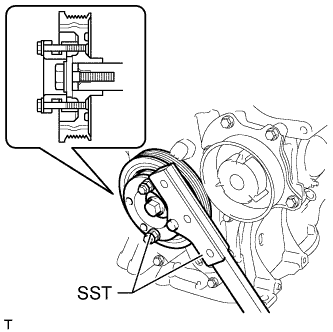
Using SST, hold the crankshaft.
for 86 mm (3.39 in.) Bolt Pitch Type:
- SST
- 09213-58014 ( 91551-80840 )
- 09330-00021
for 64 mm (2.52 in.) Bolt Pitch Type:
- SST
- 09213-54015
- 09330-00021
Tech Tips
For the 64 mm (2.52 in.) bolt pitch type, the part number of the installation bolt for SST (crankshaft pulley holding tool) is 91551-00850 (quantity: 2).
-
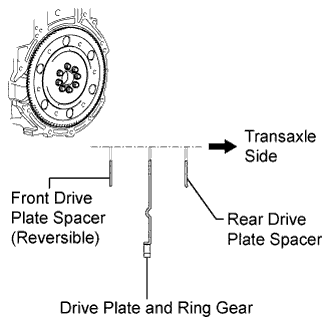
Install the front spacer, drive plate and rear spacer onto the crankshaft.
-
Clean the bolts and bolt holes.
-
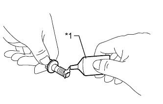
Apply adhesive to 2 or 3 threads at the end of the 8 bolts.
Adhesive Toyota Genuine Adhesive 1324, Three Bond 1324 or equivalent Text in Illustration *1 Adhesive -
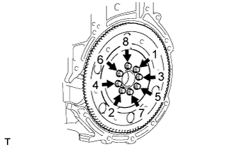
Install the 8 bolts and uniformly tighten bolts in several steps in the sequence shown in the illustration.
- Torque:
- 88 N*m { 897 kgf*cm, 65 ft.*lbf }
-
-
INSTALL CLUTCH RELEASE WITH BEARING CYLINDER ASSEMBLY (for Manual Transaxle)
-
Install the clutch release with bearing cylinder assembly Click here.
-
-
INSTALL FLYWHEEL SUB-ASSEMBLY (for Manual Transaxle)
-
Using SST, hold the crankshaft.
for 86 mm (3.39 in.) Bolt Pitch Type:
- SST
- 09213-58014 ( 91551-80840 )
- 09330-00021
for 64 mm (2.52 in.) Bolt Pitch Type:
- SST
- 09213-54015
- 09330-00021
Tech Tips
For the 64 mm (2.52 in.) bolt pitch type, the part number of the installation bolt for SST (crankshaft pulley holding tool) is 91551-00850 (quantity: 2).
-
Clean the bolts and bolt holes.
-
Apply adhesive to 2 or 3 threads at the end of the bolts.
Adhesive Toyota Genuine Adhesive 1324, Three Bond 1324 or equivalent Text in Illustration *1 Adhesive -
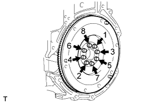
Uniformly install and tighten the 8 bolts in several steps in the sequence shown in the illustration.
- Torque:
- 49 N*m { 500 kgf*cm, 36 ft.*lbf }
-
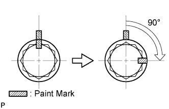
Mark the top of the bolts with paint.
-
Retighten the 8 bolts an additional 90° in the same sequence.
-
Check that the paint marks are now at a 90° angle to the top.
-
-
INSTALL CLUTCH DISC ASSEMBLY (for Manual Transaxle)
-
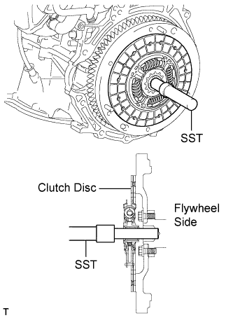
Insert SST into the clutch disc assembly, and then attach them both to the flywheel sub-assembly.
- SST
- 09301-00210
Note
Insert the clutch disc assembly in the correct direction.
-
-
INSTALL CLUTCH COVER ASSEMBLY (for Manual Transaxle)
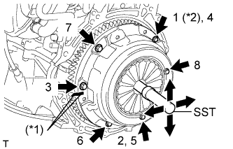
Text in Illustration *1 Matchmark *2 Temporarily Install
-
Align the matchmark on the clutch cover assembly with the one on the flywheel sub-assembly.
-
Following the order shown in the illustration, tighten the 6 bolts, starting with the bolt located near the knock pin at the top.
- SST
- 09301-00210
- Torque:
- 19 N*m { 195 kgf*cm, 14 ft.*lbf }
Tech Tips
-
Following the order in the illustration, tighten the bolts evenly one at a time.
-
Move SST up and down, right and left lightly after checking that the clutch disc assembly is in the center, and tighten the bolts.
-
-
INSPECT AND ADJUST CLUTCH COVER ASSEMBLY (for Manual Transaxle)
-
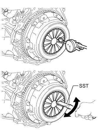
Using a dial indicator with a roller instrument, check the diaphragm spring tip alignment.
Maximum misalignment 0.5 mm (0.0196 in.) If the misalignment is more than the maximum, using SST, adjust the diaphragm spring tip alignment.
- SST
- 09333-00013
-
-
INSTALL MANUAL TRANSAXLE ASSEMBLY
-
Install the manual transaxle assembly Click here.
-
-
INSTALL CONTINUOUSLY VARIABLE TRANSAXLE ASSEMBLY
-
Install the continuously variable transaxle assembly Click here.
-
-
INSTALL ENGINE ASSEMBLY WITH TRANSAXLE
-
Install the engine assembly with transaxle Click here.
-