AUDIO AND VISUAL SYSTEM(for Radio Receiver Type) Speaker Circuit
DESCRIPTION
The sound signals amplified by the radio receiver assembly are sent to the speakers from the radio receiver assembly via the speaker circuit.
If there is a short in a speaker circuit, the radio receiver assembly detects it and stops output to the speakers.
Thus sound cannot be heard from the speakers even if there is no malfunction in the radio receiver assembly, telematics transceiver or speakers.
If a short is detected in a speaker circuit, no sound can be heard from the speakers.
WIRING DIAGRAM
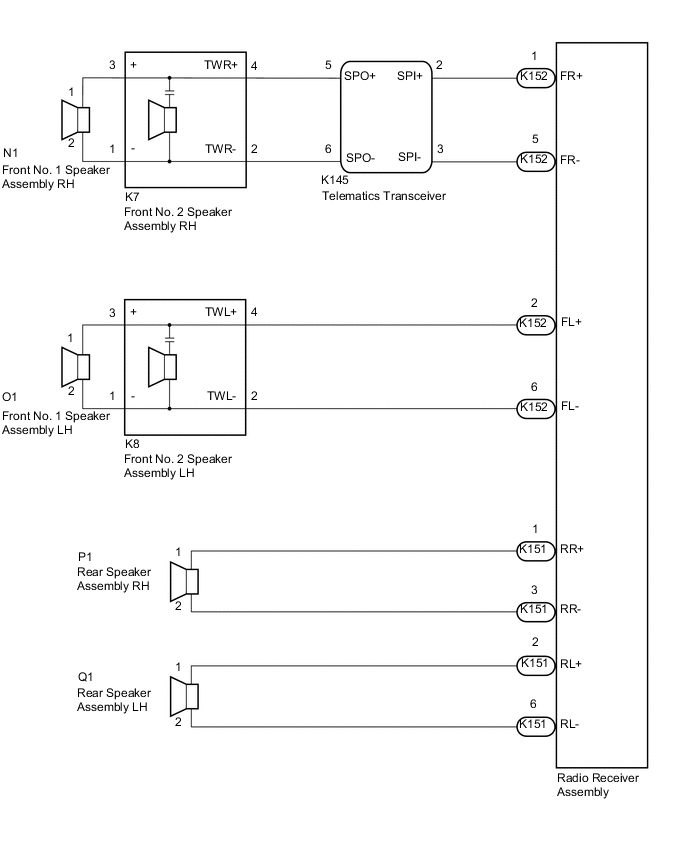
PROCEDURE
-
CHECK HARNESS AND CONNECTOR (RADIO RECEIVER ASSEMBLY- TELEMATICS TRANSCEIVER - SPEAKERS)
-
Disconnect the K152 and K151 radio receiver assembly connectors.
-
Disconnect the K145 telematics transceiver connector.
-
Disconnect the O1 and N1 front No. 1 speaker assembly connectors.
-
Disconnect the K8 and K7 front No. 2 speaker assembly connectors.
-
Disconnect the Q1 and P1 rear speaker assembly connectors.
-
Measure the resistance according to the value(s) in the table below.
Standard Resistance Tester Connection Condition Specified Condition K152-1 (FR+) - K145-2 (SPI+) Always Below 1 Ω K152-5 (FR-) - K145-3 (SPI-) Always Below 1 Ω K145-5 (SPO+) - K7-4 (TWR+) Always Below 1 Ω K145-6 (SPO-) - K7-2 (TWR-) Always Below 1 Ω K152-2 (FL+) - K8-4 (TWL+) Always Below 1 Ω K152-6 (FL-) - K8-2 (TWL-) Always Below 1 Ω K8-3 (+) - O1-1 Always Below 1 Ω K8-1 (-) - O1-2 Always Below 1 Ω K7-3 (+) - N1-1 Always Below 1 Ω K7-1 (-) - N1-2 Always Below 1 Ω K151-1 (RR+) - P1-1 Always Below 1 Ω K151-3 (RR-) - P1-2 Always Below 1 Ω K151-2 (RL+) - Q1-1 Always Below 1 Ω K151-6 (RL-) - Q1-2 Always Below 1 Ω K152-1 (FR+) or K145-2 (SPI+) - Body ground Always 10 kΩ or higher K152-5 (FR-) or K145-3 (SPI-) - Body ground Always 10 kΩ or higher K145-5 (SPO+) or K7-4 (TWR+) - Body ground Always 10 kΩ or higher K145-6 (SPO-) or K7-2 (TWR-) - Body ground Always 10 kΩ or higher K152-2 (FL+) or K8-4 (TWL+) - Body ground Always 10 kΩ or higher K152-6 (FL-) or K8-2 (TWL-) - Body ground Always 10 kΩ or higher K8-3 (+) or O1-1 - Body ground Always 10 kΩ or higher K8-1 (-) or O1-2 - Body ground Always 10 kΩ or higher K7-3 (+) or N1-1 - Body ground Always 10 kΩ or higher K7-1 (-) or N1-2 - Body ground Always 10 kΩ or higher K151-1 (RR+) or P1-1 - Body ground Always 10 kΩ or higher K151-3 (RR-) or P1-2 - Body ground Always 10 kΩ or higher K151-2 (RL+) or Q1-1 -Body ground Always 10 kΩ or higher K151-6 (RL-) or Q1-2 -Body ground Always 10 kΩ or higher Result Proceed to OK NG
NG 
REPAIR OR REPLACE HARNESS OR CONNECTOR
OK 
-
-
INSPECT TELEMATICS TRANSCEIVER
-
Remove the telematics transceiver.
-
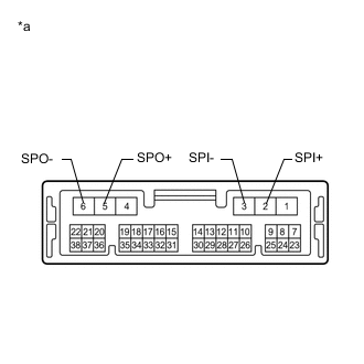
*a Component without harness connected
(Telematics Transceiver)
Measure the resistance according to the value(s) in the table below.
Standard Resistance Tester Connection Condition Specified Condition 2 (SPI+) - 5 (SPO+) Always Below 1 Ω 3 (SPI-) - 6 (SPO-) Always Below 1 Ω 2 (SPI+) - 3 (SPI-) Always 10 kΩ or higher 5 (SPO+) - 6 (SPO-) Always 10 kΩ or higher 2 (SPI+) or 5 (SPO+) - Body ground Always 10 kΩ or higher 3 (SPI-) or 6 (SPO-) - Body ground Always 10 kΩ or higher Result Proceed to OK NG
NG
REPLACE TELEMATICS TRANSCEIVER Click here
OK
-
-
INSPECT FRONT NO. 1 SPEAKER ASSEMBLY
-
Remove the front No. 1 speaker assembly.
-
Inspect the front No. 1 speaker assembly.
Result Proceed to OK NG
NG
REPLACE FRONT NO. 1 SPEAKER ASSEMBLY Click here
OK
-
-
INSPECT REAR SPEAKER ASSEMBLY
-
Remove the rear speaker assembly.
-
Inspect the rear speaker assembly.
Result Proceed to OK NG
NG
REPLACE REAR SPEAKER ASSEMBLY Click here
OK
-
-
INSPECT FRONT NO. 2 SPEAKER ASSEMBLY
-
Remove the front No. 2 speaker assembly.
-
Inspect the front No. 2 speaker assembly.
Result Proceed to OK NG
OK
END (FRONT NO. 2 SPEAKER ASSEMBLY WAS DEFECTIVE)
NG
PROCEED TO NEXT SUSPECTED AREA SHOWN IN PROBLEM SYMPTOMS TABLE Click here
-