ENGINE ASSEMBLY REMOVAL
CAUTION / NOTICE / HINT
As the engine assembly with transaxle is extremely heavy, the engine lifter may suddenly drop if the instructions listed in the repair manual are not followed. Therefore, always follow the instructions listed in the repair manual when performing this procedure.
for Manual Transaxle:
When the transaxle is removed, be sure to use a new clutch release with bearing cylinder and new installation bolts. Removal of the transaxle allows the compressed clutch release with bearing cylinder to return to its original position, and dust could damage the seal of the clutch release with bearing cylinder, possibly causing clutch fluid leaks.
PROCEDURE
DISCHARGE FUEL SYSTEM PRESSURE
REMOVE NO. 2 CYLINDER HEAD COVER
PRECAUTION
Note:After turning the ignition switch off, waiting time may be required before disconnecting the cable from the battery terminal. Therefore, make sure to read the disconnecting the cable from the battery terminal notice before proceeding with work.
DISCONNECT CABLE FROM NEGATIVE BATTERY TERMINAL
Note:When disconnecting the cable, some systems need to be initialized after the cable is reconnected.
DISCONNECT CABLE FROM POSITIVE BATTERY TERMINAL
ALIGN FRONT WHEELS FACING STRAIGHT AHEAD
REMOVE NO. 1 ENGINE UNDER COVER
REMOVE REAR ENGINE UNDER COVER RH
-
Remove the 3 clips and rear engine under cover RH.
-
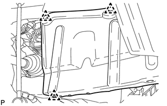
REMOVE REAR ENGINE UNDER COVER LH
-
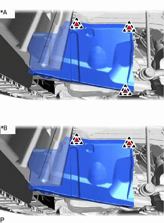
*A
for Half Cover Type
*B
for Full Cover Type
for Half Cover Type:
Remove the 3 clips and rear engine under cover LH.
for Full Cover Type:
Remove the 2 clips and rear engine under cover LH.
-
REMOVE FRONT FLOOR COVER
REMOVE NO. 2 ENGINE UNDER COVER
-
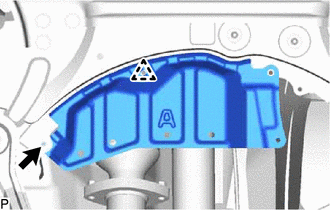
Remove the bolt, clip and No. 2 engine under cover.
-
DRAIN ENGINE COOLANT
DRAIN ENGINE OIL
DRAIN MANUAL TRANSAXLE OIL (for Manual Transaxle)
DRAIN CONTINUOUSLY VARIABLE TRANSAXLE FLUID (for CVT)
DRAIN TRANSFER OIL
REMOVE RADIATOR RESERVOIR ASSEMBLY
-
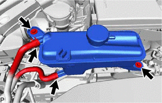
Slide the 2 hose clamps and disconnect the No. 1 and No. 2 water by-pass hoses from the radiator reservoir assembly.
Remove the 2 bolts and radiator reservoir assembly.
-
REMOVE V-RIBBED BELT
REMOVE GENERATOR ASSEMBLY
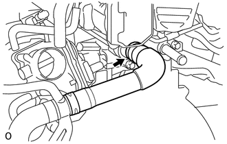
DISCONNECT NO. 2 RADIATOR HOSE
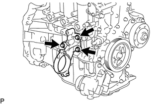
DISCONNECT COMPRESSOR ASSEMBLY WITH PULLEY
-
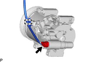
Detach the wire harness clamp and disconnect the cooler compressor connector.
-
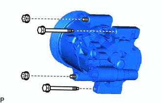
Remove the 2 bolts and 2 nuts.
-
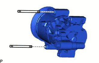
Using an E8 "TORX" socket wrench, remove the 2 stud bolts and disconnect the compressor assembly with pulley from the engine.
Tip:It is not necessary to completely remove the compressor assembly with pulley. With the hoses connected to the compressor assembly with pulley, hang the compressor assembly with pulley on the vehicle body with a rope.
-
REMOVE AIR CLEANER CAP SUB-ASSEMBLY
REMOVE AIR CLEANER CASE SUB-ASSEMBLY
REMOVE BATTERY CLAMP SUB-ASSEMBLY
REMOVE BATTERY
DISCONNECT RADIATOR HOSE SUB-ASSEMBLY
REMOVE BATTERY TRAY
REMOVE FRONT BATTERY BRACKET
REMOVE BATTERY BRACKET REINFORCEMENT
REMOVE ECM
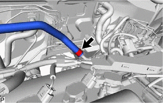
DISCONNECT NO. 1 RADIATOR HOSE
-
Slide the hose clamp and disconnect the No. 1 radiator hose from the cylinder head sub-assembly.
-
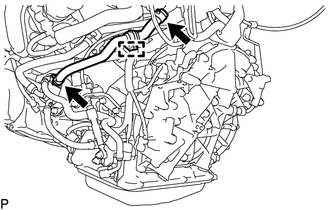
DISCONNECT FUEL TUBE SUB-ASSEMBLY
-
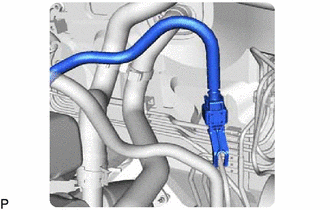
Remove the No 1 fuel pipe clamp, and then disconnect the fuel tube sub-assembly from the fuel pipe.
-
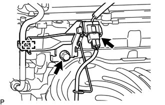
DISCONNECT WIRE HARNESS AND HOSE
-
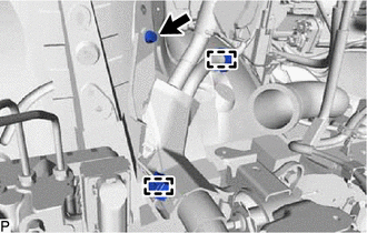
Detach the 2 wire harness clamps and remove the bolt.
-
Disconnect the 2 engine room junction block connectors and remove the nut.
-
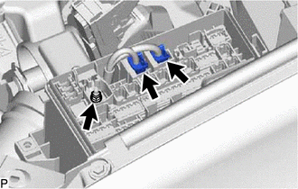
Detach the 2 claws and slide the engine wire, and then disconnect the engine wire from the engine room junction block assembly.
for Manual Transaxle:
Disconnect the terminal cap, and then remove the nut and disconnect the starter wire.
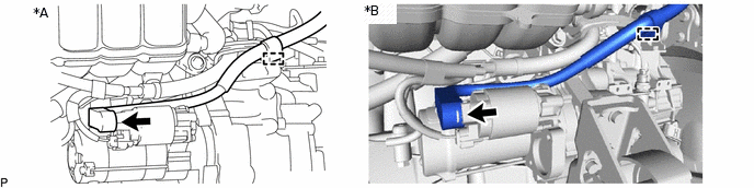
*A
w/o Stop and Start System
*B
w/ Stop and Start System
Detach the wire harness clamp.
-
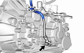
Remove the bolt.
Detach the wire harness clamp to disconnect the engine wire from the manual transaxle assembly.
for CVT:
-
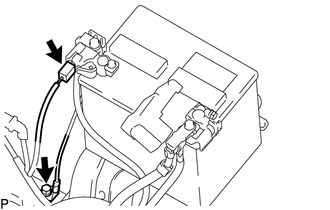
Remove the bolt and disconnect the engine wire from the body.
Disconnect the connector from the battery current sensor.
-
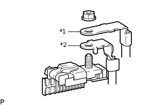
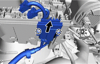
*1
Engine Room Main Wire
*2
Engine Wire
Remove the nut and disconnect the engine room main wire and engine wire from the battery positive terminal.
-
-
Slide the hose clamp and disconnect the connector tube hose from the air tube.
-
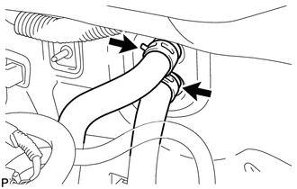
Slide the 2 clamps and disconnect the heater water outlet hose and heater water inlet hose from the heater core.
-
DISCONNECT TRANSMISSION CONTROL CABLE ASSEMBLY (for Manual Transaxle)
-
Remove the 2 clips and disconnect the top ends of the transmission control cable assembly from the manual transaxle assembly.
-
Remove the 2 clips and disconnect the 2 transmission control cable assemblies from the transmission control cable bracket.
-
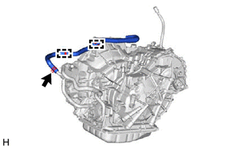
REMOVE NO. 3 WATER BY-PASS HOSE (for CVT)
-
Detach the clamp, slide the 2 hose clamps and remove the No. 3 water by-pass hose.
-
DISCONNECT TRANSMISSION CONTROL CABLE ASSEMBLY (for CVT)
Move the shift lever to N.
-
Remove the nut and disconnect the transmission control cable assembly from the control shaft lever.
Remove the clip and disconnect the transmission control cable assembly from the No. 1 transmission control cable bracket.
-
Remove the nut and disconnect the transmission control cable assembly from the transmission control cable support.
-
Remove the bolt and disconnect the transmission control cable assembly from the rear engine mounting insulator.
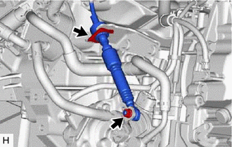
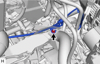
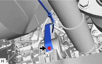
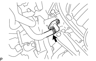
DISCONNECT CLUTCH HOSE (for Manual Transaxle)
-
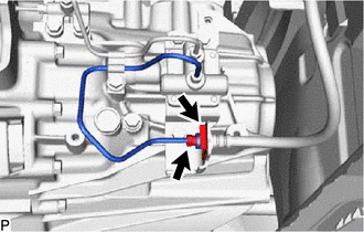
Using a 10 mm union nut wrench, disconnect the clutch hose from the accumulator to flexible hose tube.
Remove the clip and disconnect the clutch hose from the clutch hose bracket.
-
REMOVE COLUMN HOLE COVER SILENCER SHEET
DISCONNECT NO. 2 STEERING INTERMEDIATE SHAFT ASSEMBLY
DISCONNECT NO. 1 STEERING COLUMN HOLE COVER SUB-ASSEMBLY
REMOVE FRONT AXLE SHAFT NUT LH
REMOVE FRONT AXLE SHAFT NUT RH
Tip:Use the same procedure described for the LH side.
DISCONNECT FRONT SPEED SENSOR LH
DISCONNECT FRONT SPEED SENSOR RH
Tip:Use the same procedure described for the LH side.
DISCONNECT FRONT STABILIZER LINK ASSEMBLY LH
DISCONNECT FRONT STABILIZER LINK ASSEMBLY RH
Tip:Use the same procedure described for the LH side.
DISCONNECT TIE ROD END SUB-ASSEMBLY LH
DISCONNECT TIE ROD END SUB-ASSEMBLY RH
Tip:Use the same procedure described for the LH side.
DISCONNECT FRONT LOWER NO. 1 SUSPENSION ARM SUB-ASSEMBLY LH
DISCONNECT FRONT LOWER NO. 1 SUSPENSION ARM SUB-ASSEMBLY RH
Tip:Use the same procedure described for the LH side.
REMOVE FRONT DRIVE SHAFT ASSEMBLY LH
REMOVE FRONT DRIVE SHAFT HOLE SNAP RING LH
REMOVE FRONT DRIVE SHAFT ASSEMBLY RH
DISCONNECT HEATED OXYGEN SENSOR (for Bank 1 Sensor 2)
REMOVE FRONT EXHAUST PIPE ASSEMBLY
REMOVE PROPELLER WITH CENTER BEARING SHAFT ASSEMBLY
REMOVE FLYWHEEL HOUSING UNDER COVER
REMOVE DRIVE PLATE AND TORQUE CONVERTER SETTING BOLT (for CVT)
REMOVE FRONT SUSPENSION MEMBER REINFORCEMENT LH
-
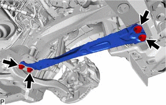
Remove the 4 bolts and front suspension member reinforcement LH.
-
REMOVE FRONT SUSPENSION MEMBER REINFORCEMENT RH
-
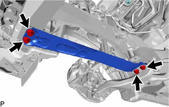
Remove the 4 bolts and front suspension member reinforcement RH.
-
INSTALL ENGINE HANGER
-
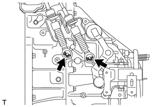
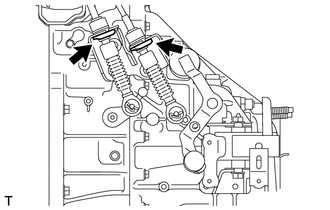
Disconnect the air fuel ratio sensor connector and detach the clamp to disconnect the fuel tube from the air fuel ratio sensor bracket.
Remove the bolt and air fuel ratio sensor bracket.
-
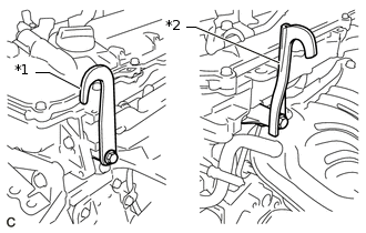
*1
No. 1 Engine Hanger
*2
No. 2 Engine Hanger
Install the 2 engine hangers with 2 bolts as shown in the illustration.
43 N*m
438 kgf*cm
32 ft.*lbf
Tip:No. 1 Engine Hanger
12281-37021
No. 2 Engine Hanger
12282-37011
Bolt
91552-81050
-
REMOVE ENGINE ASSEMBLY WITH TRANSAXLE
-
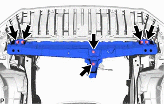
Remove the 6 bolts and front crossmember sub-assembly.
Remove the through bolt, nut and front engine mounting insulator.
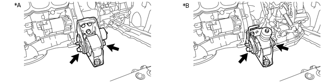
*A
for Manual Transaxle
*B
for CVT
Set an engine lifter underneath the engine.
Note:Place the engine on wooden blocks or equivalent so that the engine is level.
-
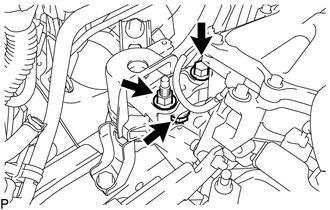
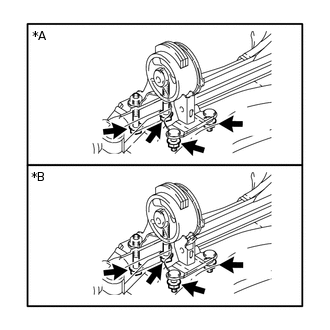
Remove the bolt and 2 nuts, and disconnect the engine mounting insulator sub-assembly RH.
Remove the bolt and nut, and disconnect the engine mounting insulator LH.
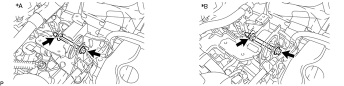
*A
for Manual Transaxle
*B
for CVT
-
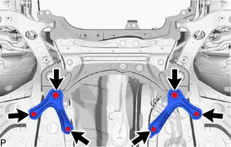
Remove the 6 bolts and front suspension member rear brace RH and LH.
-
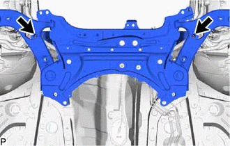
Remove the 2 bolts and front suspension crossmember sub-assembly.
Operate the engine lifter and slowly remove the engine from the vehicle.
Note:Make sure that the engine is clear of all wiring and hoses.
While lowering the engine from the vehicle, do not allow it to contact the vehicle.
Attach an engine sling device and hang the engine with a chain block.
-
Remove the through bolt and front suspension crossmember sub-assembly from the engine.
Note:Do not damage any engine or transaxle components.
Tip:Raise the engine with transaxle assembly while keeping it level.
-
REMOVE STEERING GEAR HEAT INSULATOR (for RHD)
REMOVE NO. 5 WATER BY-PASS HOSE (for CVT)
-
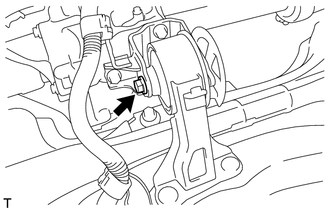
Slide the clip and disconnect the No. 5 water by-pass hose from the No. 3 water by-pass pipe.
-
Slide the clip and disconnect the No. 5 water by-pass hose from the oil cooler.
Detach the 2 clamps to remove the No. 5 water by-pass hose.
-
DISCONNECT NO. 1 TRANSMISSION OIL COOLER HOSE (for CVT)
DISCONNECT NO. 2 TRANSMISSION OIL COOLER HOSE (for CVT)
REMOVE OIL COOLER (for CVT)
REMOVE TRANSMISSION OIL COOLER BRACKET (for CVT)
REMOVE STARTER ASSEMBLY
REMOVE FLYWHEEL HOUSING SIDE COVER
REMOVE TRANSFER ASSEMBLY
REMOVE CONTINUOUSLY VARIABLE TRANSAXLE ASSEMBLY (for CVT)
REMOVE MANUAL TRANSAXLE ASSEMBLY (for Manual Transaxle)
FIX ENGINE ASSEMBLY
Using wooden blocks or plate lift attachments, set the engine on a flat surface.
Note:Place wooden blocks or plate lift attachments so that the engine is level.
Never install attachments to the oil pan of the engine assembly or transmission as doing so may deform the oil pan.
Perform this step while supporting the engine assembly using a sling device and chain block.
REMOVE DRIVE PLATE AND RING GEAR SUB-ASSEMBLY (for CVT)
REMOVE CLUTCH COVER ASSEMBLY (for Manual Transaxle)
REMOVE CLUTCH DISC ASSEMBLY (for Manual Transaxle)
REMOVE CLUTCH TUBE (for Manual Transaxle)
REMOVE CLUTCH RELEASE BLEEDER SUB-ASSEMBLY (for Manual Transaxle)
REMOVE CLUTCH RELEASE WITH BEARING CYLINDER ASSEMBLY (for Manual Transaxle)
REMOVE FLYWHEEL SUB-ASSEMBLY (for Manual Transaxle)
REMOVE ENGINE WIRE
Remove the engine wire from the engine.
INSTALL ENGINE TO ENGINE STAND
Note:Pay attention to the angle of the sling device as the engine assembly or engine hangers may be damaged or deformed if the angle is incorrect.
With the exception of installing the engine assembly to an engine stand or removing the engine assembly from an engine stand, do not perform any work on the engine while it is suspended, as doing so is dangerous.
Install the engine to an engine stand with the bolts.
Remove the 2 bolts and 2 engine hangers.
REMOVE DRIVE SHAFT BEARING BRACKET
-
Remove the 3 bolts and drive shaft bearing bracket.
-
REMOVE REAR ENGINE MOUNTING INSULATOR
Tip:Perform this procedure only when replacement of the rear engine mounting insulator is necessary.
-
*A
for Manual Transaxle
*B
for CVT
Remove the 2 bolts, 2 nuts and rear engine mounting insulator.
-
REMOVE ENGINE MOUNTING INSULATOR SUB-ASSEMBLY RH
Tip:Perform this procedure only when replacement of the engine mounting insulator sub-assembly RH is necessary.
-
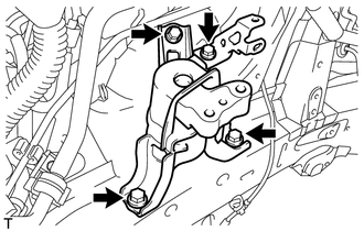
Remove the bolt and radiator reservoir bracket.
Remove the 3 bolts and engine mounting insulator sub-assembly RH.
-
REMOVE ENGINE MOUNTING INSULATOR LH
Tip:Perform this procedure only when replacement of the engine mounting insulator LH is necessary.
-
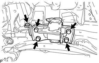
Remove the bolt and wire harness clamp bracket.
Remove the 4 bolts and engine mounting insulator LH.
-