ECD SYSTEM(for Swirl Control Valve) ECM Power Source Circuit
| DTC Code | DTC Name |
|---|---|
| ECM Power Source Circuit |
DESCRIPTION
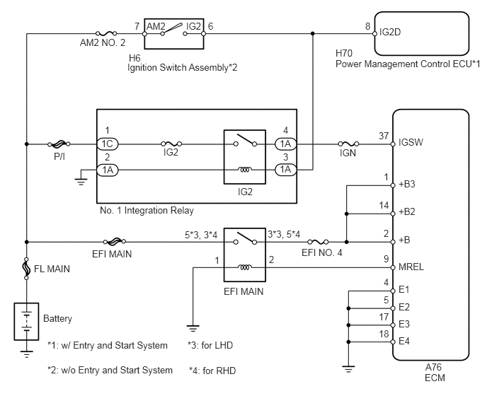
When the ignition switch is turned to ON, the battery voltage is applied to the IGSW terminal of the ECM. The output signal from the MREL terminal of the ECM causes a current to flow to the EFI MAIN relay coil, closing the EFI MAIN relay contacts and supplying power to terminal +B, +B2 and +B3 of the ECM.
WIRING DIAGRAM
CAUTION / NOTICE / HINT
When replacing the ECM, the ECM needs Registration and Initialization (Click here).
Inspection the fuses for circuits related to this system before performing the following inspection procedure.
When the ECM must be replaced, before replacing the ECM, perform the "Learning Values Save" function using the GTS. Then after installing the new ECM, perform all of the initialization/registrations for the "Learning Values Write" function by following the instructions shown on the tester display.
PROCEDURE
CHECK HARNESS AND CONNECTOR (POWER SOURCE)
Remove the No. 1 integration relay from the engine room No. 1 relay block.
Remove the EFI MAIN relay from the engine room No. 1 relay block.
Measure the voltage according to the value(s) in the table below.
Standard Voltage
Tester Connection
Condition
Specified Condition
1C-1 - Body ground
Always
11 to 14 V
5 (EFI MAIN relay holder) - Body ground*1
3 (EFI MAIN relay holder) - Body ground*2
Always
11 to 14 V
*1: for LHD
*2: for RHD
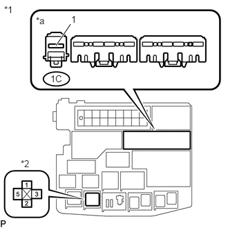
Table 1. Text in Illustration *1
Engine Room No. 1 Relay Block
*2
EFI MAIN Relay
*a
Front view of wire harness connector
(to No. 1 Integration Relay)
Measure the resistance according to the value(s) in the table below.
Standard Resistance
Tester Connection
Condition
Specified Condition
1A-2 - Body ground
Always
Below 1 Ω
1 (EFI MAIN relay holder) - Body ground
Always
Below 1 Ω
REPAIR OR REPLACE HARNESS OR CONNECTOR (ENGINE ROOM NO. 1 RELAY BLOCK - BATTERY)
INSPECT NO. 1 INTEGRATION RELAY (IG2)
Inspect the No. 1 integration relay (IG2) (Click hereClick here).
REPLACE NO. 1 INTEGRATION RELAY
INSPECT EFI MAIN RELAY
Inspect the EFI MAIN relay (Click hereClick here).
REPLACE EFI MAIN RELAY
CHECK HARNESS AND CONNECTOR (ENGINE ROOM NO. 1 RELAY BLOCK - ECM)
Disconnect the ECM connector.
Remove the EFI MAIN relay from the engine room No. 1 relay block.
Measure the resistance according to the value(s) in the table below.
Standard Resistance (for LHD)
Tester Connection
Condition
Specified Condition
A76-9 (MREL) - 2 (EFI MAIN relay holder)
Always
Below 1 Ω
A76-2 (+B) - 3 (EFI MAIN relay holder)
Always
Below 1 Ω
A76-14 (+B2) - 3 (EFI MAIN relay holder)
Always
Below 1 Ω
A76-1 (+B3) - 3 (EFI MAIN relay holder)
Always
Below 1 Ω
A76-9 (MREL) or 2 (EFI MAIN relay holder) - Body ground
Always
10 kΩ or higher
A76-2 (+B) or 3 (EFI MAIN relay holder) - Body ground
Always
10 kΩ or higher
A76-14 (+B2) or 3 (EFI MAIN relay holder) - Body ground
Always
10 kΩ or higher
A76-1 (+B3) or 3 (EFI MAIN relay holder) - Body ground
Always
10 kΩ or higher
Standard Resistance (for RHD)
Tester Connection
Condition
Specified Condition
A76-9 (MREL) - 2 (EFI MAIN relay holder)
Always
Below 1 Ω
A76-2 (+B) - 5 (EFI MAIN relay holder)
Always
Below 1 Ω
A76-14 (+B2) - 5 (EFI MAIN relay holder)
Always
Below 1 Ω
A76-1 (+B3) - 5 (EFI MAIN relay holder)
Always
Below 1 Ω
A76-9 (MREL) or 2 (EFI MAIN relay holder) - Body ground
Always
10 kΩ or higher
A76-2 (+B) or 5 (EFI MAIN relay holder) - Body ground
Always
10 kΩ or higher
A76-14 (+B2) or 5 (EFI MAIN relay holder) - Body ground
Always
10 kΩ or higher
A76-1 (+B3) or 5 (EFI MAIN relay holder) - Body ground
Always
10 kΩ or higher
REPAIR OR REPLACE HARNESS OR CONNECTOR
CHECK HARNESS AND CONNECTOR (ECM - BODY GROUND)
-
Disconnect the ECM connector.
Measure the resistance according to the value(s) in the table below.
Standard Resistance
Tester Connection
Condition
Specified Condition
A76-4 (E1) - Body ground
Always
Below 1 Ω
A76-5 (E2) - Body ground
Always
Below 1 Ω
A76-17 (E3) - Body ground
Always
Below 1 Ω
A76-18 (E4) - Body ground
Always
Below 1 Ω
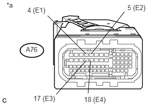
Table 2. Text in Illustration *a
Front view of wire harness connector
(to ECM)
REPAIR OR REPLACE HARNESS OR CONNECTOR
-
CHECK HARNESS AND CONNECTOR (IGSW TERMINAL VOLTAGE)
Disconnect the ECM connector.
Turn the ignition switch to ON.
Measure the voltage according to the value(s) in the table below.
Standard Voltage
Tester Connection
Switch Condition
Specified Condition
A76-37 (IGSW) - Body ground
Ignition switch ON
11 to 14 V
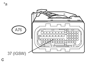
Table 3. Text in Illustration *a
Front view of wire harness connector
(to ECM)
CHECK HARNESS AND CONNECTOR (ECM - NO. 1 INTEGRATION RELAY)
Disconnect the ECM connector.
Remove the No. 1 integration relay from the engine room No. 1 relay block.
Measure the resistance according to the value(s) in the table below.
Standard Resistance
Tester Connection
Condition
Specified Condition
A76-37 (IGSW) - 1A-4
Always
Below 1 Ω
A76-37 (IGSW) or 1A-4 - Body ground
Always
10 kΩ or higher
Table 4. Result Result
Proceed to
NG
A
OK (w/ Entry and Start System)
B
OK (w/o Entry and Start System)
C
REPAIR OR REPLACE HARNESS OR CONNECTOR
CHECK HARNESS AND CONNECTOR (IGNITION SWITCH ASSEMBLY - NO. 1 INTEGRATION RELAY)Click here
CHECK HARNESS AND CONNECTOR (POWER MANAGEMENT CONTROL ECU - NO. 1 INTEGRATION RELAY)
Disconnect the power management control ECU connector.
Remove the No. 1 integration relay from the engine room No. 1 relay block.
Measure the resistance according to the value(s) in the table below.
Standard Resistance
Tester Connection
Condition
Specified Condition
H70-8 (IG2D) - 1A-3
Always
Below 1 Ω
H70-8 (IG2D) or 1A-3 - Body ground
Always
10 kΩ or higher
REPAIR OR REPLACE HARNESS OR CONNECTOR
CHECK HARNESS AND CONNECTOR (IGNITION SWITCH ASSEMBLY - NO. 1 INTEGRATION RELAY)
Disconnect the ignition switch assembly connector.
Remove the No. 1 integration relay from the engine room No. 1 relay block.
Measure the resistance according to the value(s) in the table below.
Standard Resistance
Tester Connection
Condition
Specified Condition
H6-6 (IG2) - 1A-3
Always
Below 1 Ω
H6-6 (IG2) or 1A-3 - Body ground
Always
10 kΩ or higher
REPAIR OR REPLACE HARNESS OR CONNECTOR
INSPECT IGNITION SWITCH ASSEMBLY
Inspect the ignition switch assembly (Click here).
REPAIR OR REPLACE HARNESS OR CONNECTOR (IGNITION SWITCH ASSEMBLY - BATTERY)