DIFFERENTIAL CARRIER OIL SEAL REPLACEMENT

-
DRAIN DIFFERENTIAL OIL
-
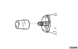
Remove the filler plug and gasket.
-
Remove the drain plug and gasket, and drain the oil.
-
Install the drain plug with a new gasket.
- Torque:
- 49 N*m { 500 kgf*cm, 36 ft.*lbf }
-
-
REMOVE PROPELLER SHAFT ASSEMBLY (for Super Long Wheelbase)
-
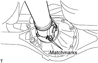
Put matchmarks on both flanges.
-
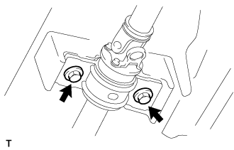
Remove the 4 nuts, bolts and washers.
Tech Tips
If the flange connection is hard to separate, temporarily tighten one nut only and evenly tap the flange with a brass bar and hammer to separate the propeller with center bearing shaft assembly from the differential companion flange.
-
Remove the 2 bolts and center support bearing assembly No.1.
-
Remove the propeller with center bearing shaft assembly.
-
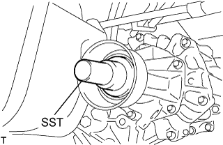
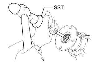
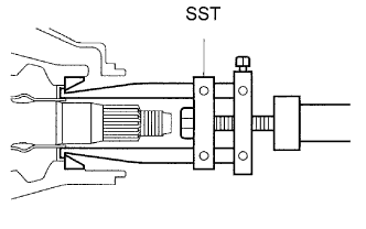
Insert SST in the transmission to prevent oil leakage.
Note
Do not damage the oil seal.
-
Use the following SST for the automatic transmission.
- SST
- 09325-40010
-
Use the following SST for the manual transmission.
- SST
- 09325-20010
-
-
-
REMOVE PROPELLER SHAFT ASSEMBLY (for Long Wheelbase)
-
Put matchmarks on both flanges.
-
Remove the 4 nuts, bolts and washers.
Tech Tips
If the flange connection is hard to separate, temporarily tighten one nut only and evenly tap the flange with a brass bar and hammer to separate the propeller shaft assembly from the differential companion flange.
-
Remove the propeller shaft assembly.
-
Insert SST in the transmission to prevent oil leakage.
Note
Do not damage the oil seal.
-
Use the following SST for the automatic transmission
- SST
- 09325-40010
-
Use the following SST for the manual transmission
- SST
- 09325-20010
-
-
-
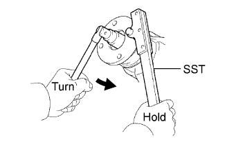
REMOVE REAR DRIVE PINION NUT
-
Using SST and a hammer, release the staked part of the drive pinion nut.
- SST
- 09930-00010
Note
-
Be sure to use SST with the tapered surface facing the shaft.
-
Do not grind the tip of the SST with a grinder etc.
-
Completely loosen the staked part of the nut when removing it.
-
Do not damage the threads of the drive pinion.
-
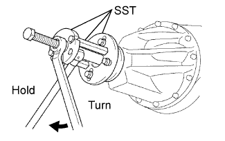
Using SST to hold the flange, remove the drive pinion nut.
- SST
- 09330-00021
-
-
REMOVE REAR DRIVE PINION COMPANION FLANGE SUB-ASSEMBLY
-
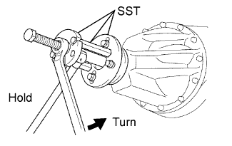
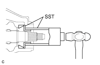
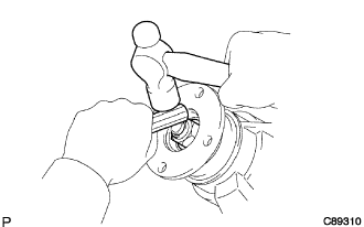
Using SST, remove the companion flange.
- SST
- 09950-30012 ( 09951-03010, 09953-03010, 09954-03010, 09955-03030, 09956-03040 )
Note
Apply grease to the threads and tip of the SST center bolt before use.
-
-
REMOVE REAR DIFFERENTIAL CARRIER OIL SEAL
-
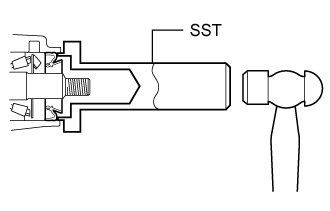
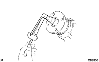
Using SST, remove the oil seal from the differential carrier.
- SST
- 09308-10010
Note
Apply grease to the threads and tip of the SST center bolt before use.
-
-
REMOVE REAR DIFFERENTIAL DRIVE PINION OIL SLINGER
-
REMOVE REAR DRIVE PINION FRONT BEARING
-
Using SST, remove the inner race of the rear drive pinion front tapered roller bearing from the drive pinion.
- SST
- 09556-22010
Note
Apply grease to the threads and tip of the SST center bolt before use.
-
Using SST, remove the outer race of the rear drive pinion front tapered roller bearing from the differential carrier.
- SST
- 09308-00010
-
-
REMOVE DIFFERENTIAL OIL STORAGE RING
-
Using a screwdriver and hammer, tap out the oil storage ring.
-
-
REMOVE REAR DIFFERENTIAL DRIVE PINION BEARING SPACER
-
INSTALL REAR DIFFERENTIAL DRIVE PINION BEARING SPACER
-
Install a new drive pinion bearing spacer to the drive pinion.
Note
Be sure to face the larger inner diameter side rearward as shown in the illustration.
-
-
INSTALL DIFFERENTIAL OIL STORAGE RING
-
Using a brass bar and hammer, tap in a new oil storage ring.
Note
Be careful not to damage the oil storage ring.
-
-
INSTALL REAR DRIVE PINION FRONT BEARING
-
Using SST and hammer, tap in the outer race of the rear drive pinion front tapered roller bearing.
- SST
- 09316-60011 ( 09316-00011, 09316-00021 )
-
Install the inner race of the rear drive pinion front tapered roller bearing.
-
-
INSTALL REAR DIFFERENTIAL DRIVE PINION OIL SLINGER
-
INSTALL REAR DIFFERENTIAL CARRIER OIL SEAL
-
Using SST and a hammer, install a new oil seal.
- SST
- 09554-22010
Oil seal drive in depth 0.4 to 1.0 mm (0.0158 to 0.0393 in.) -
Apply MP grease to the oil seal lip.
-
-
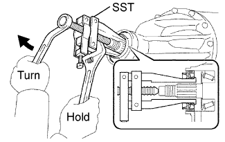
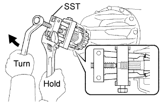
INSTALL REAR DRIVE PINION COMPANION FLANGE SUB-ASSEMBLY
-
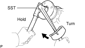
Using SST, install the companion flange to the drive pinion.
- SST
- 09950-30012 ( 09951-03010, 09953-03010, 09954-03010, 09955-03030, 09956-03040 )
Note
Apply grease to the threads and tip of the SST center bolt before use.
-
Coat the threads of a new drive pinion nut with hypoid gear oil LSD.
-
Using SST, hold the flange.
- SST
- 09330-00021
-
Using a socket wrench (30 mm) and torque wrench, gradually tighten the drive pinion nut within the adjustment range of the differential drive pinion preload.
- Torque:
- 370 N*m { 3,770 kgf*cm, 273 ft.*lbf, or less }
-
-
INSPECT AND ADJUST DIFFERENTIAL DRIVE PINION PRELOAD
-
Using a torque wrench, measure the preload of the drive pinion.
Preload (at starting) New bearing 1.01 to 1.60 N*m (11 to 16 kgf*cm, 9 to 14 in.*lbf) Reused bearing 0.52 to 0.81 N*m (6 to 8 kgf*cm, 5 to 7 in.*lbf) -
If the preload is less than the specified minimum value, check the preload while retightening the drive pinion nut by 5 to 10° to adjust it into the specified range.
-
If the preload is less than the specified minimum value even when the tightening torque of the drive pinion nut is greater than the specified maximum value, loosen the nut and check that the threads of the drive pinion nut and drive pinion are not stripped.
-
If the threads are not stripped, replace the bearing spacer. Apply hypoid gear oil LSD to the threads of the drive pinion and repeat the procedure.
-
-
INSTALL REAR DRIVE PINION NUT
-
Using a chisel and hammer, stake the drive pinion nut.
-
-
INSTALL PROPELLER SHAFT ASSEMBLY (for Super Long Wheelbase)
-
Remove the SST from the extension housing.
-
Install the propeller with center bearing shaft assembly in the extension housing.
-
Install the center support bearing assembly No.1, and temporarily tighten the 2 bolts.
-
Align the matchmarks on the propeller shaft flange and differential flange.
-
Install the propeller shaft assembly with the 4 nuts, 4 bolts and 4 washers.
- Torque:
- 74 N*m { 755 kgf*cm, 54 ft.*lbf }
-
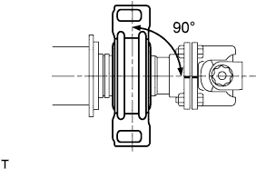
Check that the center line of the bracket is at right angles to the shaft axial direction.
-
Adjust the center support bearing assembly No.1.
Tech Tips
-
With the vehicle unladen, adjust the center support bearing No.1 to maintain the angles, as shown.
-
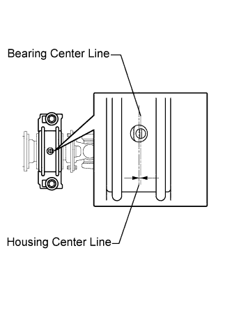
In the same conditions, check the center line in the axial direction. Adjust the bearing if necessary.
-
The center bearing center line and center bearing housing center line must be adjusted to within -1.0 to 1.0 mm (-0.0394 to 0.0394 in.) of each other in the vehicle's longitudinal direction with the vehicle unladen.
-
-
Tighten the 2 bolts.
- Torque:
- 36 N*m { 369 kgf*cm, 27 ft.*lbf }
-
-
INSTALL PROPELLER SHAFT ASSEMBLY (for Long Wheelbase)
-
Remove the SST from the extension housing.
-
Install the propeller shaft assembly in the extension housing.
-
Align the matchmarks on the propeller shaft flange and differential flange.
-
Install the propeller shaft assembly with the 4 nuts, 4 bolts and 4 washers.
- Torque:
- 74 N*m { 755 kgf*cm, 54 ft.*lbf }
-
-
FILL DIFFERENTIAL OIL
-
Remove the differential filler plug and gasket.
-
Fill with oil.
Oil grade Toyota Genuine Differential Gear oil GL-5 or equivalent Recommended oil viscosity Above -18°C (0°F) SAE 90 Below -18°C (0°F) SAE 80W or 80W-90 Standard differential oil capacity Body Type Specified Condition Standard Body 3.10 liters (3.28 US qts, 2.73 Imp. qts) Wide Body 3.25 liters (3.43 US qts, 2.86 Imp. qts) -
Check the oil level.
-
Install the differential filler plug with a new gasket.
- Torque:
- 49 N*m { 500 kgf*cm, 36 ft.*lbf }
Note
After replacing the oil, recheck the oil level after driving.
-
-
INSPECT AND ADJUST DIFFERENTIAL OIL
-
Stop the vehicle on a level place.
-
Remove the differential filler plug and gasket.
-
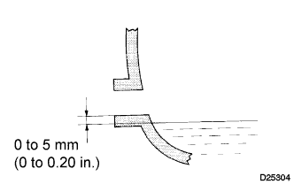
Check that the oil surface is within 5 mm (0.20 in.) of the lowest position of the inner surface of the differential filler plug opening.
Note
-
Excessively large or small amounts of oil may cause trouble.
-
After replacing oil, drive the vehicle and check the oil level.
Tech Tips
If necessary, fill the rear differential carrier with hypoid gear oil.
-
-
Check for oil leakage when the oil level is low.
-
Install the differential filler plug and a new gasket.
- Torque:
- 49 N*m { 500 kgf*cm, 36 ft.*lbf }
-