SPEED LIMITER SYSTEM TERMINALS OF ECM
CHECK ECM (for 1KR-FE)
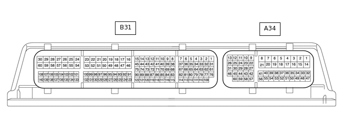 Tip:
Tip:The standard voltage, resistance and waveform between each pair of the ECM terminals is shown in the table below. The appropriate conditions for checking each pair of the terminals is also indicated. The result of checks should be compared with the standard voltage, resistance and waveform for each pair of the terminals as displayed in the Specified Condition column. The illustration above can be used as a reference to identify the ECM terminal locations.
Terminal No. (Symbol)
Wiring Color
Terminal Description
Condition
Specified Condition
A34-59 (ASLM) - A34-30 (ECCS)
G - W
Adjustable speed limiter switch (Cruise control main switch) circuit
Adjustable speed limiter switch (Cruise control main switch) (ON-OFF button) released
1 MΩ or higher
A34-59 (ASLM) - A34-30 (ECCS)
G - W
Adjustable speed limiter switch (Cruise control main switch) circuit
Adjustable speed limiter switch (Cruise control main switch) (ON-OFF button) pushed
Below 2.5 Ω
A34-60 (CCS) - A34-30 (ECCS)
B - W
Adjustable speed limiter switch (Cruise control main switch) circuit
+ RES switch operated
235 to 245 Ω
A34-60 (CCS) - A34-30 (ECCS)
B - W
Adjustable speed limiter switch (Cruise control main switch) circuit
- SET switch operated
617 to 643 Ω
A34-60 (CCS) - A34-30 (ECCS)
B - W
Adjustable speed limiter switch (Cruise control main switch) circuit
CANCEL switch operated
1509 to 1571 Ω
A34-15 (BATT) - Body ground
SB - Body ground
Power source circuit
Always
11 to 14 V
A34-37 (IGSW) - Body ground
B - Body ground
IG power source circuit
Ignition switch ON
11 to 14 V
Ignition switch off
Below 1 V
A34-4 (E1) - Body ground
W-B - Body ground
Ground
Always
Below 1 Ω
CHECK ECM (for 1PP)
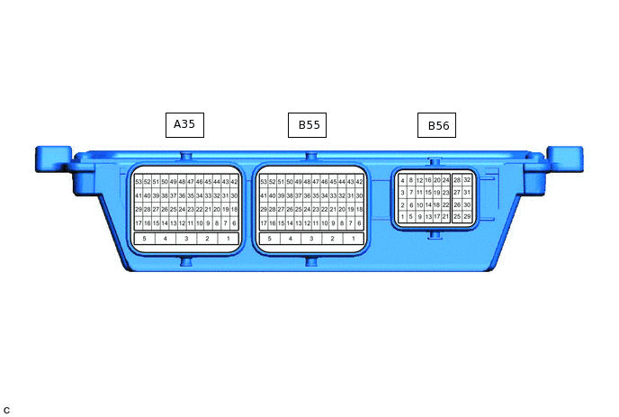 Tip:
Tip:The standard voltage, resistance and waveform between each pair of the ECM terminals is shown in the table below. The appropriate conditions for checking each pair of the terminals is also indicated. The result of checks should be compared with the standard voltage, resistance and waveform for each pair of the terminals as displayed in the Specified Condition column. The illustration above can be used as a reference to identify the ECM terminal locations.
Terminal No. (Symbol)
Wiring Color
Terminal Description
Condition
Specified Condition
A35-32 (SPDL) - A35-49 (SPDL)
B - W
Adjustable speed limiter switch (Cruise control main switch) circuit
Adjustable speed limiter switch (Cruise control main switch) (ON-OFF button) released
1 MΩ or higher
A35-32 (SPDL) - A35-49 (SPDL)
B - W
Adjustable speed limiter switch (Cruise control main switch) circuit
Adjustable speed limiter switch (Cruise control main switch) (ON-OFF button) pushed
Below 2.5 Ω
A35-32 (SPDL) - A35-49 (SPDL)
B - W
Adjustable speed limiter switch (Cruise control main switch) circuit
+ switch operated
235 to 245 Ω
A35-32 (SPDL) - A35-49 (SPDL)
B - W
Adjustable speed limiter switch (Cruise control main switch) circuit
- switch operated
617 to 643 Ω
A35-32 (SPDL) - A35-49 (SPDL)
B - W
Adjustable speed limiter switch (Cruise control main switch) circuit
RES/CAN switch operated
1509 to 1571 Ω