ELECTRONIC CONTROLLED AUTOMATIC TRANSMISSION SYSTEM (for 1KD-FTV) TERMINALS OF ECU
Tech Tips
Each ECU terminal's standard voltage is shown in the table below.
In the table, first follow the information under "Condition". Look under "Symbols (Terminal No.)" for the terminals to be inspected. The standard voltage between the terminals is shown under "Specified Condition".
Use the illustration above as a reference for the ECU terminals.
-
ECM
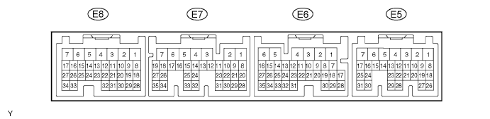
Symbols (Terminal No.) Wiring Color Terminal Description Condition Specified Condition NSW (E5-6) - E1 (E7-7) L-Y - BR PNP switch signal Ignition switch ON and shift lever on P or N Below 3 V NSW (E5-6) - E1 (E7-7) L-Y - BR PNP switch signal Ignition switch ON and shift lever not on P or N 9 to 14 V STP (E6-15) - E1 (E7-7) G-W - BR Stop light switch signal Brake pedal is depressed 7.5 to 14 V STP (E6-15) - E1 (E7-7) G-W - BR Stop light switch signal Brake pedal is released Below 1.5 V STA (E5-7) - E1 (E7-7) B-Y - BR Starter signal Ignition switch ON and shift lever on P or N Below 3 V STA (E5-7) - E1 (E7-7) B-Y - BR Starter signal Ignition switch ON and shift lever not on P or N 9 to 14 V CAN+ (E6-22) - E1 (E7-7) V - BR CAN communication line Ignition switch ON Pulse generation
(see waveform 6)
CAN- (E6-21) - E1 (E7-7) P - BR CAN communication line Ignition switch ON Pulse generation
(see waveform 7)
-
TCM
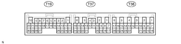
Symbols (Terminal No.) Wiring Color Terminal Description Condition Specified Condition IG2 (T38-6) - E1 (T19-1) B-O - BR Ignition switch Ignition switch ON 9 to 14 V NSW (T19-12) - E1 (T19-1) L-Y - BR PNP switch signal Ignition switch ON and shift lever on P or N Below 3 V NSW (T19-12) - E1 (T19-1) L-Y - BR PNP switch signal Ignition switch ON and shift lever not on P or N 9 to 14 V S2 (T19-17) - E1 (T19-1) W-L - BR S2 solenoid signal Ignition switch ON Below 1.5 V S2 (T19-17) - E1 (T19-1) W-L - BR S2 solenoid signal 2nd or 3rd gear 9 to 14 V S2 (T19-17) - E1 (T19-1) W-L - BR S2 solenoid signal 1st or O/D gear Below 1.5 V S1 (T19-18) - E1 (T19-1) GR - BR S1 solenoid signal Ignition switch ON 9 to 14 V S1 (T19-18) - E1 (T19-1) GR - BR S1 solenoid signal 1st or 2nd gear 9 to 14 V S1 (T19-18) - E1 (T19-1) GR - BR S1 solenoid signal 3rd or O/D gear Below 1.5 V SLT+ (T19-20) - SLT- (T19-19) G-Y - L-B SLT solenoid signal Ignition switch ON Below 3 V SLT+ (T19-20) - SLT- (T19-19) G-Y - L-B SLT solenoid signal Engine idle speed Pulse generation
(see waveform 1)
SL (T19-16) - E1 (T19-1) G - BR SL solenoid signal Vehicle speed 65 km/h (40 mph), lock-up (ON to OFF) Pulse generation
(see waveform 2)
SL (T19-16) - E1 (T19-1) G - BR SL solenoid signal Vehicle driving under lock-up condition 9 to 14 V SP2+ (T19-30) - SP2- (T19-29) R - G No. 2 vehicle speed sensor (SP2) signal Vehicle speed 20 km/h (12 mph) Pulse generation
(see waveform 3)
NC0+ (T19-3) - NC0- (T19-2) V - P O/D direct clutch speed sensor (NC0) signal Engine is idling Pulse generation
(see waveform 4)
THOC (T19-24) - E2 (T19-23) BR - B-Y ATF temperature sensor signal ATF temperature: 115°C (239°F) or more Below 1.5 V L (T37-10) - E1 (T19-1) G-R - BR L shift position switch signal Ignition switch ON and transfer shift lever on L 7.5 to 14 V L (T37-10) - E1 (T19-1) G-R - BR L shift position switch signal Ignition switch ON and transfer shift lever not on L Below 1.5 V 2 (T37-11) - E1 (T19-1) L - BR 2 shift position switch signal Ignition switch ON and transfer shift lever on 2 7.5 to 14 V 2 (T37-11) - E1 (T19-1) L - BR 2 shift position switch signal Ignition switch ON and transfer shift lever not on 2 Below 1.5 V D (T37-8) - E1 (T19-1) G-Y - BR D shift position switch signal Ignition switch ON and transfer shift lever on D or 3 7.5 to 14 V D (T37-8) - E1 (T19-1) G-Y - BR D shift position switch signal Ignition switch ON and transfer shift lever not on D or 3 Below 1.5 V R (T37-9) - E1 (T19-1) R-Y - BR R shift position switch signal Ignition switch ON and transfer shift lever on R 7.5 to 14 V R (T37-9) - E1 (T19-1) R-Y - BR R shift position switch signal Ignition switch ON and transfer shift lever not on R Below 1.5 V SPD1 (T38-25) - E1 (T19-1) V-R - BR Speed signal Vehicle speed 20 km/h (12 mph) Pulse generation
(see waveform 5)
STP (T38-14) - E1 (T19-1) G-W - BR Stop light switch signal Ignition switch ON and brake pedal is depressed 7.5 to 14 V STP (T38-14) - E1 (T19-1) G-W - BR Stop light switch signal Ignition switch ON and brake pedal is released Below 1.5 V 3 (T37-12) - E1 (T19-1) G-O - BR 3 shift position switch signal Ignition switch ON and transfer shift lever on 3 7.5 to 14 V 3 (T37-12) - E1 (T19-1) G-O - BR 3 shift position switch signal Ignition switch ON and transfer shift lever not on 3 Below 1.5 V STA (T19-11) - E1 (T19-1) B-Y - BR Starter signal Cranking 6 V or more STA (T19-11) - E1 (T19-1) B-Y - BR Starter signal Ignition switch ON and shift lever in P or N Below 2 V SIL (T37-23) - E1 (T19-1) R-Y - BR Terminal SIL of DLC3 Connect intelligent tester to DLC3 Pulse generation WFSE (T37-24) - E1 (T19-1) W - BR Terminal SIL of DLC3 Ignition switch ON 9 to 14 V L4 (T37-15) - E1 (T19-1) G-W - BR L4 shift position switch signal Ignition switch ON and transfer shift lever on L4 Below 1.5 V L4 (T37-15) - E1 (T19-1) G-W - BR L4 shift position switch signal Ignition switch ON and transfer shift lever not on L4 7.5 to 14 V TFN (T37-16) - E1 (T19-1) W-G - BR N shift position switch signal Ignition switch ON and transfer shift lever on N Below 1.5 V TFN (T37-16) - E1 (T19-1) W-G - BR N shift position switch signal Ignition switch ON and transfer shift lever not on N 7.5 to 14 V CAN+ (T38-21) - E1 (T19-1) V - BR CAN communication line Ignition switch ON Pulse generation
(see waveform 6)
CAN- (T38-20) - E1 (T19-1) P - BR CAN communication line Ignition switch ON Pulse generation
(see waveform 7)
-
Waveform 1 (Reference)
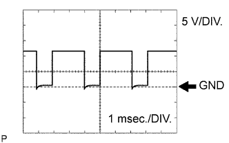
Item Content Symbols (Terminal No.) SLT+ (T19-20) - SLT- (T19-19) Tool Setting 5 V/DIV., 1 msec./DIV. Condition Engine idle speed -
Waveform 2 (Reference)
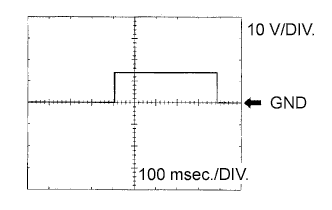
Item Content Symbols (Terminal No.) SL (T19-16) - E1 (T19-1) Tool Setting 10 V/DIV., 100 msec./DIV. Condition Vehicle speed 65 km/h (40 mph), lock-up (ON to OFF) -
Waveform 3 (Reference)
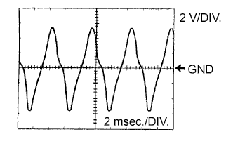
Item Content Symbols (Terminal No.) SP2+ (T19-30) - SP2- (T19-29) Tool Setting 2 V/DIV., 2 msec./DIV. Condition Vehicle speed 20 km/h (12 mph) -
Waveform 4 (Reference)
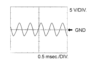
Item Content Symbols (Terminal No.) NC0+ (T19-3) - NC0- (T19-2) Tool Setting 5 V/DIV., 0.5 msec./DIV. Condition Engine is idling -
Waveform 5 (Reference)
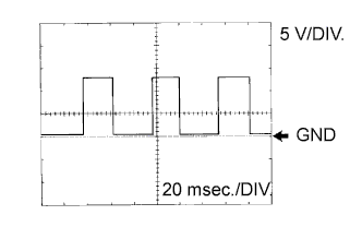
Item Content Symbols (Terminal No.) SPD1 (T38-25) - E1 (T19-1) Tool Setting 5 V/DIV., 20 msec./DIV. Condition Vehicle speed 20 km/h (12 mph) -
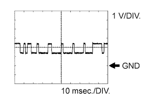
Waveform 6 (Reference)
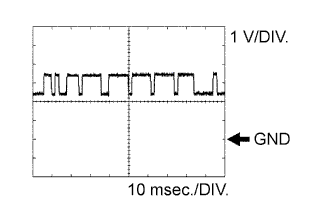
Item Content Symbols (Terminal No.) CAN+ (E6-22) - E1 (E7-7)
CAN+ (T38-21) - E1 (T19-1)
Tool Setting 1 V/DIV., 10 msec./DIV. Condition Ignition switch ON -
Waveform 7 (Reference)
Item Content Symbols (Terminal No.) CAN- (E6-21) - E1 (E7-7)
CAN- (T38-20) - E1 (T19-1)
Tool Setting 1 V/DIV., 10 msec./DIV. Condition Ignition switch ON