TRANSMISSION CONTROL CABLE REPLACEMENT
-
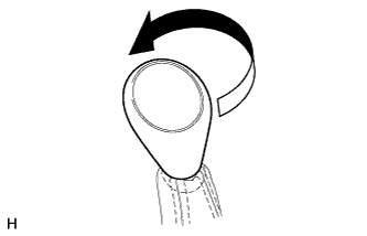
REMOVE TRANSFER SHIFT LEVER KNOB SUB-ASSEMBLY
-
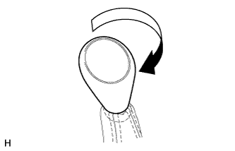
Twist the shift lever knob in the direction indicated by the arrow and remove it.
-
-
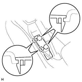
REMOVE PARKING BRAKE HOLE COVER SUB-ASSEMBLY
-
Detach the 4 claws and remove the parking brake hole cover.
-
-
REMOVE UPPER CONSOLE PANEL SUB-ASSEMBLY
-
Detach the 12 claws and remove the upper console panel.
Note
Be careful not to damage the instrument panel and console box with the claws of the upper console panel.
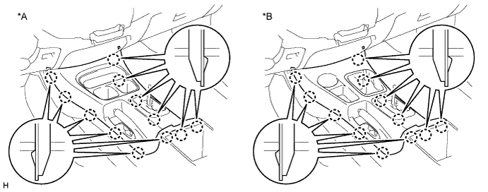
Text in Illustration *A for 2WD *B for 4WD
-
-
REMOVE CONSOLE BOX ASSEMBLY
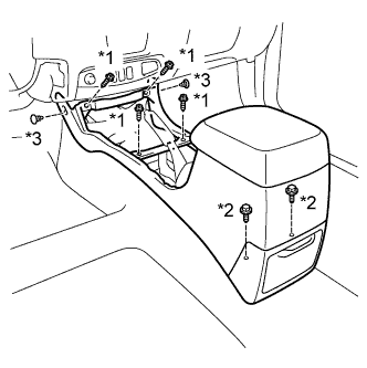
Text in Illustration *1 Screw *2 Bolt *3 Clip
-
Remove the 4 screws and 2 bolts.
-
Using a clip remover, remove the 2 clips and console box.
-
-
REMOVE TRANSMISSION CONTROL CABLE ASSEMBLY
-
Move the shift lever to L.
-
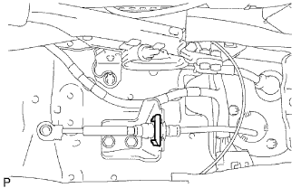
Disconnect the control cable from the shift lever.
-
Remove the lock clip and disconnect the control cable from the bracket.
-
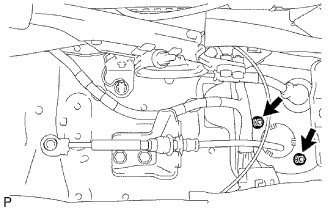
Remove the 2 nuts and disconnect the control cable from the vehicle body.
-
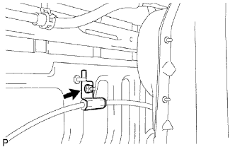
Remove the nut and disconnect the control cable from the vehicle body.
-
Remove the nut and clip and disconnect the control cable.
-
-
INSTALL TRANSMISSION CONTROL CABLE ASSEMBLY
-
Install the control cable with the nut.
- Torque:
- 14 N*m { 143 kgf*cm, 10 ft.*lbf }
-
Connect the control cable to the vehicle body with the nut.
- Torque:
- 5.5 N*m { 56 kgf*cm, 49 in.*lbf }
-
Connect the control cable to the vehicle body with the 2 nuts.
- Torque:
- 5.5 N*m { 56 kgf*cm, 49 in.*lbf }
-
Connect the control cable to the bracket with the lock clip.
-
Move the shift lever to L.
-
Install the control cable to the shift lever.
-
-
ADJUST SHIFT LEVER POSITION
-
Move the shift lever to N.
-
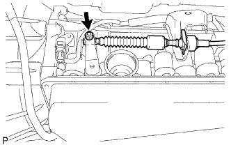
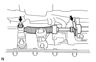
Remove the nut and disconnect the control cable.
-
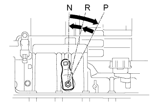
Turn the control shaft lever clockwise until it stops, and then turn it counterclockwise 2 notches to set it to the N position.
-
While holding the control shaft lever slightly toward the R position side, connect the cable with the nut.
- Torque:
- 14 N*m { 143 kgf*cm, 10 ft.*lbf }
-
-
INSPECT SHIFT LEVER POSITION
-
Move the shift lever to N.
-
Remove the nut and disconnect the control cable.
-
Turn the control shaft lever clockwise until it stops, and then turn it counterclockwise 2 notches to set it to the N position.
-
While holding the control shaft lever slightly toward the R position side, connect the cable with the nut.
- Torque:
- 14 N*m { 143 kgf*cm, 10 ft.*lbf }
-
-
INSTALL CONSOLE BOX ASSEMBLY
Text in Illustration *1 Screw *2 Bolt *3 Clip
-
Install the console box with the 4 screws and 2 bolts.
-
Install the 2 clips.
-
-
INSTALL UPPER CONSOLE PANEL SUB-ASSEMBLY
-
Attach the 12 claws to install the upper console panel.
Text in Illustration *A for 2WD *B for 4WD
-
-
INSTALL PARKING BRAKE HOLE COVER SUB-ASSEMBLY
-
Attach the 4 claws to install the parking brake hole cover.
-
-
INSTALL TRANSFER SHIFT LEVER KNOB SUB-ASSEMBLY
-
Install the shift lever knob and twist it in the direction indicated by the arrow.
-