CYLINDER HEAD GASKET INSTALLATION
PROCEDURE
INSPECT CYLINDER HEAD SET BOLT
INSTALL CYLINDER HEAD GASKET
-
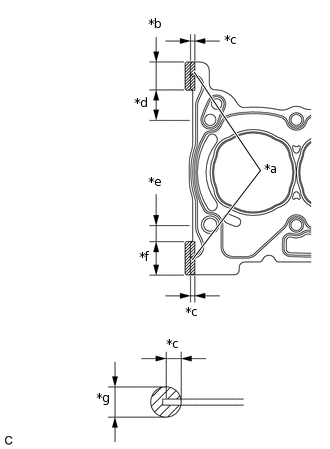
*a
Seal Packing
*b
23.0 to 27.0 mm (0.906 to 1.06 in.)
*c
1.0 to 3.0 mm (0.0394 to 0.118 in.)
*d
28.0 mm (1.10 in.)
*e
13.0 mm (0.512 in.)
*f
28.0 to 32.0 mm (1.10 to 1.26 in.)
*g
4.0 mm (0.157 in.)
Apply seal packing to a new cylinder head gasket as shown in the illustration.
Seal Packing
Toyota Genuine Seal Packing Black, Three Bond 1207B or equivalent
Note:Remove any oil from the cylinder block sub-assembly, cylinder head gasket and cylinder head sub-assembly.
Apply seal packing to the edge of the cylinder head gasket.
Place the cylinder head gasket on the cylinder block sub-assembly.
Note:Install the cylinder head sub-assembly within 3 minutes and tighten the bolts within 15 minutes of applying seal packing.
-
INSTALL CYLINDER HEAD SUB-ASSEMBLY
Note:Place the cylinder head sub-assembly gently in order not to damage the gasket.
Place the cylinder head sub-assembly on the cylinder block sub-assembly.
Install the 8 plate washers to the cylinder head sub-assembly.
Note:Do not drop the washers into the cylinder head sub-assembly.
-
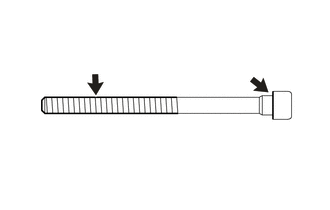
Apply engine oil to the threads and seating surface of each cylinder head set bolt.
-
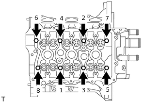
Using an 8 mm bi-hexagon wrench, uniformly install and tighten the 8 cylinder head set bolts in several steps in the order shown in the illustration.
32 N*m
326 kgf*cm
24 ft.*lbf
-
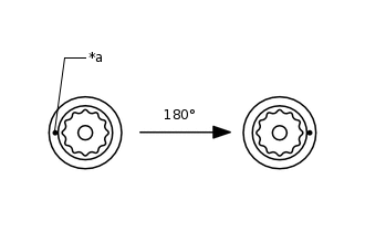
*a
Paint Mark
Mark the front of each cylinder head set bolt with paint.
Tighten the cylinder head set bolts by an additional 180° as shown in the illustration.
Check that the paint marks are now at a 180° angle from the front.
-
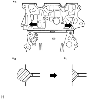
*a
Direction to wipe off
*b
Before wiping off
*c
After wiping off
Wipe off any seal packing that has seeped out from the contact surface between the cylinder head sub-assembly and cylinder block sub-assembly.
Note:Be sure to wipe off the seal packing from inside to outside, parallel to the joint line.
Be sure to avoid clogging the bolt holes when wiping off the seal packing.
INSTALL NO. 2 CAMSHAFT
INSTALL CAMSHAFT
INSTALL OIL CONTROL VALVE FILTER
INSTALL CAMSHAFT BEARING CAP
INSTALL CAMSHAFT TIMING SPROCKET ASSEMBLY
INSTALL BRACKET
INSTALL TIMING CHAIN GUIDE
INSTALL CRANKSHAFT TIMING SPROCKET
INSTALL CHAIN SUB-ASSEMBLY
INSTALL TIMING CHAIN TENSION ARM
INSTALL NO. 1 CHAIN TENSIONER ASSEMBLY
INSTALL TIMING CHAIN COVER OIL SEAL
INSTALL TIMING CHAIN COVER SUB-ASSEMBLY
INSTALL CRANKSHAFT PULLEY
INSTALL OIL PAN SUB-ASSEMBLY
Remove any old seal packing remaining on the sealing surfaces before applying seal packing.
Clean the contact surfaces of the oil pan sub-assembly and cylinder block sub-assembly, and confirm that no oil, moisture or other foreign matter on the surfaces.
-
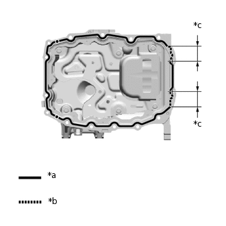
*a
Continuous Line Area (3.0 to 4.0 mm (0.118 to 0.157 in.))
*b
Dashed Line Area (5.0 to 6.0 mm (0.197 to 0.236 in.))
*c
39.5 mm (1.56 in.)
Apply seal packing to the oil pan sub-assembly as shown in the illustration.
Seal Packing
Toyota Genuine Seal Packing Black, Three Bond 1207B or equivalent
Note:Apply seal packing to the contact surfaces between the timing chain cover sub-assembly and cylinder block sub-assembly, and between the rear engine oil seal retainer and cylinder block sub-assembly.
Install the oil pan sub-assembly within 3 minutes and tighten the bolts within 10 minutes of applying seal packing.
-
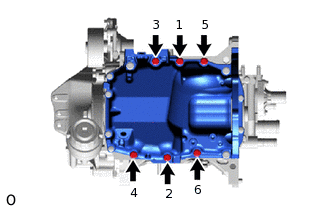
Install the 6 bolts in the order shown in the illustration.
24 N*m
245 kgf*cm
18 ft.*lbf
-
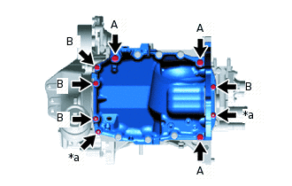
*a
Nut
Install the 7 bolts and 2 nuts.
Bolt (A)
24 N*m
245 kgf*cm
18 ft.*lbf
Bolt (B), Nut
10 N*m
102 kgf*cm
7 ft.*lbf
INSTALL WATER BY-PASS PIPE
INSTALL CYLINDER HEAD COVER GASKET
INSTALL CYLINDER HEAD COVER SUB-ASSEMBLY
INSTALL NO. 1 IGNITION COIL
INSTALL CRANKSHAFT POSITION SENSOR
INSTALL CAMSHAFT TIMING OIL CONTROL VALVE ASSEMBLY (for Intake Side)
INSTALL CAMSHAFT TIMING OIL CONTROL VALVE ASSEMBLY (for Exhaust Side)
INSTALL EXHAUST MANIFOLD (TWC: Catalyst)
INSTALL MANIFOLD STAY
INSTALL ENGINE OIL LEVEL DIPSTICK GUIDE
INSTALL ENGINE OIL LEVEL DIPSTICK
INSTALL OIL LEVEL GAUGE GUIDE OIL HOSE
INSTALL WATER BY-PASS HOSE ASSEMBLY
INSTALL ENGINE HANGER
REMOVE ENGINE FROM ENGINE STAND