THEFT DETERRENT SYSTEM TERMINALS OF ECU
-
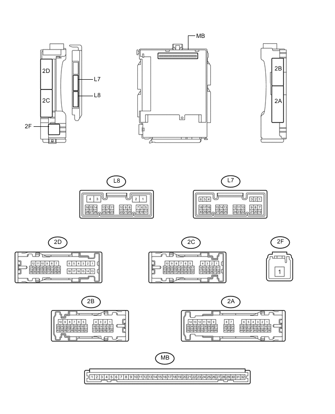
CHECK MAIN BODY ECU (MULTIPLEX NETWORK BODY ECU) AND INSTRUMENT PANEL JUNCTION BLOCK ASSEMBLY
-
Disconnect the main body ECU (multiplex network body ECU) connectors.
-
Measure the resistance and voltage according to the value(s) in the table below.
Tech Tips
Measure the value(s) on the wire harness side with the connectors disconnected.
Tester Connection Wiring Color Terminal Description Condition Specified Condition MB-31 (ALTB) - Body ground - Auxiliary battery power supply Power switch off 11 to 14 V MB-30 (BECU) - Body ground - Auxiliary battery power supply Power switch off 11 to 14 V MB-29 (ACC) - Body ground - Ignition power supply (ACC signal) Power switch on (ACC) → off 11 to 14 V → Below 1 V MB-32 (IG) - Body ground - Ignition power supply (IG signal) Power switch on (IG) → off 11 to 14 V → Below 1 V MB-11 (GND1) - Body ground - Ground Always Below 1 Ω L8-3 (GND2) - Body ground W-B - Body ground Ground Always Below 1 Ω MB-2 (FLCY) - Body ground - Front door courtesy light switch LH input Front door LH closed (OFF) → open (ON) 10 kΩ or higher → Below 1 Ω MB-4 (FRCY) - Body ground - Front door courtesy light switch RH input Front door RH closed (OFF) → open (ON) 10 kΩ or higher → Below 1 Ω L7-6 (LRCY) - Body ground G - Body ground Rear door courtesy light switch LH or RH input Rear door LH or RH closed (OFF) → open (ON) 10 kΩ or higher → Below 1 Ω L7-19 (BCTY) - Body ground L - Body ground Back door courtesy switch input Back door closed (OFF) → open (ON) 10 kΩ or higher → Below 1 Ω MB-20 (HCTY) - Body ground - Engine hood courtesy switch input Engine hood open (ON) → closed (OFF) Below 1 Ω → 10 kΩ or higher If the result is not as specified, there may be a malfunction in the wire harness.
-
Reconnect the main body ECU (multiplex network body ECU) connectors.
-
Measure the voltage and resistance according to the value(s) in the table below.
Tester Connection Wiring Color Terminal Description Condition Specified Condition L7-7 (LSFL) - Body ground GR - Body ground Front door LH unlock detection switch input Front door LH unlocked Below 1 V L7-7 (LSFL) - Body ground GR - Body ground Front door LH unlock detection switch input Front door LH locked Pulse generation L7-18 (LSFR) - Body ground LG - Body ground Front door RH unlock detection switch input Front door RH unlocked Below 1 V L7-18 (LSFR) - Body ground LG - Body ground Front door RH unlock detection switch input Front door RH locked Pulse generation 2D-25 (LSR) - Body ground GR - Body ground Rear door LH unlock detection switch input Rear door LH unlocked Below 1 V 2D-25 (LSR) - Body ground GR - Body ground Rear door LH unlock detection switch input Rear door LH locked Pulse generation 2B-29 (LSR) - Body ground GR - Body ground Rear door RH unlock detection switch input Rear door RH unlocked Below 1 V 2B-29 (LSR) - Body ground GR - Body ground Rear door RH unlock detection switch input Rear door RH locked Pulse generation L8-8 (SSW1) - Body ground*1 G - Body ground Intrusion sensor cancel switch signal Intrusion sensor cancel switch not pushed Below 1 V L8-8 (SSW1) - Body ground*1 G - Body ground Intrusion sensor cancel switch signal Intrusion sensor cancel switch pushed Pulse generation L8-12 (ISIF) - Body ground*1 V - Body ground Intrusion sensor (theft warning ultrasonic sensor) signal input No moving object detected by sensor 11 to 14 V L8-12 (ISIF) - Body ground*1 V - Body ground Intrusion sensor (theft warning ultrasonic sensor) signal input Moving object detected by sensor during arming preparation state or armed state Below 1 V 2B-15 (GPBS) - Body ground*1 V - Body ground Glass breakage sensor drive Always
(Quarter window assembly RH, quarter window assembly LH or back door glass)
Below 1 V 2A-51 (IND) - Body ground G - Body ground Security indicator light up Security indicator light on (It lights up only for 27.5 sec. in alarm sounding state.) 3 to 10 V L8-18 (SSCL) - Body ground*1 L - Body ground Theft warning siren drive Theft warning siren sounding
(Theft deterrent system in alarm sounding state)
Pulse generation
(Below 1 V ← → 11 to 14 V)
2C-39 (SH) - Body ground*2 Y - Body ground Security horn drive Security horn sounding
(Theft deterrent system is in alarm sounding state)
Pulse generation
(Below 1 V ← → 11 to 14 V)
2C-24 (HORN) - Body ground SB - Body ground Vehicle horn drive Vehicle horns sounding
(Theft deterrent system in alarm sounding state)
Pulse generation
(Below 1 V ← → 11 to 14 V)
-
*1: w/ Intrusion Sensor Cancel Switch
-
*2: w/o Intrusion Sensor Cancel Switch
If the result is not as specified, the main body ECU (multiplex network body ECU) may have a malfunction.
-
-