LIGHTING SYSTEM Illumination Circuit
| DTC Code | DTC Name |
|---|---|
| Illumination Circuit |
DESCRIPTION
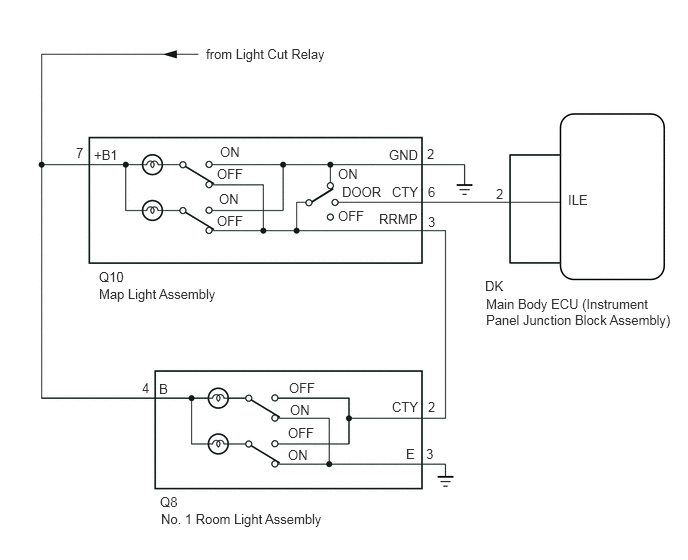
The main body ECU receives information regarding all the door courtesy light switches and door lock position switches, and turns on the room lights.
WIRING DIAGRAM
CAUTION / NOTICE / HINT
Inspect the fuses and bulbs for circuits related to this system before performing the following inspection procedure.
PROCEDURE
PERFORM ACTIVE TEST USING INTELLIGENT TESTER
Connect the intelligent tester to the DLC3.
Turn the ignition switch to ON.
Turn the intelligent tester on.
Turn the map light switch to the DOOR position.
Close all the doors (all door courtesy light switches turn off).
Enter the following menus: Body / Main Body / Active Test / Illuminated Entry System.
Use the Active Test to check the operation of the illuminated entry system.
Table 1. Main Body Tester Display
Test Part
Control Range
Diagnostic Note
Illuminated Entry System
All parts illuminated by illuminated entry system
ON/OFF
-
OK
The illuminated entry system operates normally when operating it using the Active Test.
INSPECT MAP LIGHT ASSEMBLY
-
Remove the map light assembly (Click here).
Measure the resistance according to the value(s) in the table below.
Standard Resistance
Tester Connection
Switch Condition
Specified Condition
7 (+B1) - 6 (CTY)
Map light switch off
Door switch not in door position
10 kΩ or higher
7 (+B1) - 6 (CTY)
Map light switch off
Door switch in door position
Below 1 Ω
7 (+B1) - 2 (GND)
Map light switch off
Door switch in on position
Below 1 Ω
7 (+B1) - 2 (GND)
Map light switch off
Door switch not in on position
10 kΩ or higher
7 (+B1) - 2 (GND)
Map light switch on
Below 1 Ω
7 (+B1) - 3 (RRMP)
Map light switch on
Door switch not in on position
10 kΩ or higher
7 (+B1) - 3 (RRMP)
Map light switch off
Door switch not in on position
Below 1 Ω
-
CHECK HARNESS AND CONNECTOR (MAP LIGHT - MAIN BODY ECU, BATTERY AND BODY GROUND)
-
Disconnect the DK main body ECU connector.
Disconnect the Q10 map light connector.
Measure the voltage and resistance according to the value(s) in the table below.
Standard Voltage
Tester Connection
Condition
Specified Condition
Q10-7 (+B1) - Body ground
Battery saving control (interior light auto cut function) not operating
11 to 14 V
Standard Resistance
Tester Connection
Condition
Specified Condition
Q10-6 (CTY) - DK-2 (ILE)
Always
Below 1 Ω
Q10-6 (CTY) - Body ground
Always
10 kΩ or higher
Q10-2 (GND) - Body ground
Always
Below 1 Ω
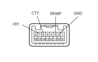
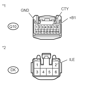
Table 2. Text in Illustration *1
Front view of wire harness connector
(to Map Light Assembly)
*2
Front view of wire harness connector
(to Main Body ECU)
REPAIR OR REPLACE HARNESS OR CONNECTOR
-
INSPECT NO. 1 ROOM LIGHT ASSEMBLY
-
Remove the No. 1 room light assembly (Click here).
Measure the resistance according to the value(s) in the table below.
Standard Resistance
Tester Connection
Switch Condition
Specified Condition
4 (B) - 3 (E)
Off
10 kΩ or higher
4 (B) - 2 (CTY)
Off
Below 1 Ω
4 (B) - 3 (E)
On
Below 1 Ω
4 (B) - 2 (CTY)
On
10 kΩ or higher
-
CHECK HARNESS AND CONNECTOR (NO. 1 ROOM LIGHT - MAP LIGHT, BATTERY AND BODY GROUND)
-
Disconnect the Q10 map light connector.
Disconnect the Q8 No. 1 room light connector.
Measure the voltage and resistance according to the value(s) in the table below.
Standard Voltage
Tester Connection
Condition
Specified Condition
Q8-4 (B) - Body ground
Battery saving control (interior light auto cut function) not operating
11 to 14 V
Standard Resistance
Tester Connection
Condition
Specified Condition
Q8-2 (CTY) - Q10-3 (RRMP)
Always
Below 1 Ω
Q8-2 (CTY) - Body ground
Always
10 kΩ or higher
Q8-3 (E) - Body ground
Always
Below 1 Ω
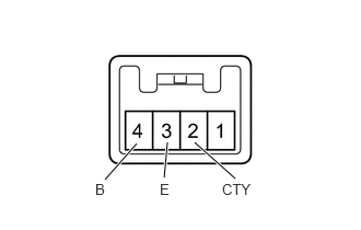
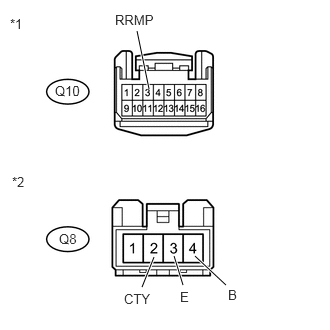
Table 3. Text in Illustration *1
Front view of wire harness connector
(to Map Light Assembly)
*2
Front view of wire harness connector
(to No. 1 Room Light Assembly)
REPLACE MAIN BODY ECU (INSTRUMENT PANEL JUNCTION BLOCK ASSEMBLY)
REPAIR OR REPLACE HARNESS OR CONNECTOR
-