LIGHTING SYSTEM Door Unlock Detection Switch Circuit
DESCRIPTION
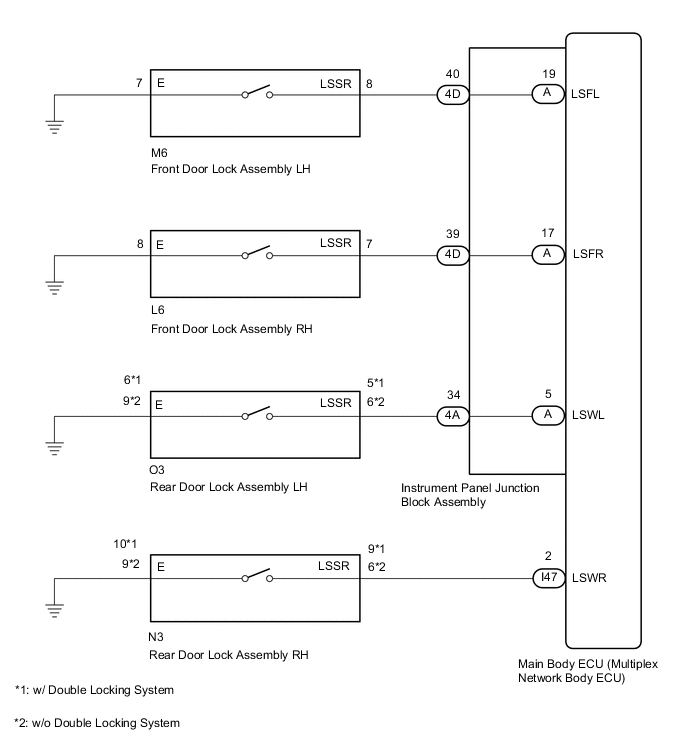
The main body ECU (multiplex network body ECU) detects the condition of each door unlock detection switch.
WIRING DIAGRAM
CAUTION / NOTICE / HINT
Note
-
If the main body ECU (multiplex network body ECU) is replaced, refer to the Service Bulletin.
-
As the door control battery is installed between the vehicle battery and main body ECU (multiplex network body ECU), first perform the inspections in On-Vehicle Inspection to confirm that there are no malfunctions in the power source circuit for the main body ECU (multiplex network body ECU) before performing this troubleshooting procedure.*
*: w/ Door Control Battery
PROCEDURE
-
READ VALUE USING GTS (DOOR LOCK POS)
-
Using the GTS, read the Data List.
Body Electrical > Main Body > Data ListTester Display Measurement Item Range Normal Condition Diagnostic Note FR Door Lock Pos Front door unlock detection switch RH signal UNLOCK or LOCK UNLOCK: Front door RH unlocked
LOCK: Front door RH locked
- FL Door Lock Pos Front door unlock detection switch LH signal UNLOCK or LOCK UNLOCK: Front door LH unlocked
LOCK: Front door LH locked
- RR-Door Lock Pos SW Rear door unlock detection switch RH signal ON or OFF ON: Rear door RH unlocked
OFF: Rear door RH locked
- RL-Door Lock Pos SW Rear door unlock detection switch LH signal ON or OFF ON: Rear door LH unlocked
OFF: Rear door LH locked
-
Body Electrical > Main Body > Data ListTester Display FR Door Lock Pos FL Door Lock Pos RR-Door Lock Pos SW RL-Door Lock Pos SW OK The display is as specified in the normal condition column. Result Result Proceed to OK A NG (Front door unlock detection switch RH does not operate) B NG (Front door unlock detection switch LH does not operate) C NG (Rear door unlock detection switch RH does not operate) D NG (Rear door unlock detection switch LH does not operate) E
A 
PROCEED TO NEXT SUSPECTED AREA SHOWN IN PROBLEM SYMPTOMS TABLE Click here
C 
INSPECT FRONT DOOR LOCK ASSEMBLY LH Click here
D
INSPECT REAR DOOR LOCK ASSEMBLY RH Click here
E
INSPECT REAR DOOR LOCK ASSEMBLY LH Click here
B 
-
-
INSPECT FRONT DOOR LOCK ASSEMBLY RH
-
Remove the front door lock assembly RH.
-
Inspect the front door lock assembly RH.
Result Proceed to OK NG
NG
REPLACE FRONT DOOR LOCK ASSEMBLY RH Click here
OK
-
-
CHECK HARNESS AND CONNECTOR (FRONT DOOR LOCK ASSEMBLY RH - INSTRUMENT PANEL JUNCTION BLOCK ASSEMBLY AND BODY GROUND)
-
Disconnect the 4D instrument panel junction block assembly connector.
-
Disconnect the L6 front door lock assembly RH connector.
-
Measure the resistance according to the value(s) in the table below.
Standard Resistance Tester Connection Condition Specified Condition L6-7 (LSSR) - 4D-39 Always Below 1 Ω L6-8 (E) - Body ground Always Below 1 Ω L6-7 (LSSR) or 4D-39 - Body ground Always 10 kΩ or higher Result Proceed to OK NG
NG
REPAIR OR REPLACE HARNESS OR CONNECTOR
OK
-
-
INSPECT INSTRUMENT PANEL JUNCTION BLOCK ASSEMBLY
-
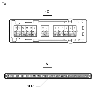
*a Component without harness connected
(Instrument Panel Junction Block Assembly)
Remove the instrument panel junction block assembly.
for LHD:
for RHD:
-
Remove the main body ECU (multiplex network body ECU) from the instrument panel junction block assembly.
for LHD:
for RHD:
-
Measure the resistance according to the value(s) in the table below.
Standard Resistance Tester Connection Condition Specified Condition A-17 (LSFR) - 4D-39 Always Below 1 Ω Result Proceed to OK NG
OK
REPLACE MAIN BODY ECU (MULTIPLEX NETWORK BODY ECU) for LHD: REPLACE MAIN BODY ECU (MULTIPLEX NETWORK BODY ECU) Click here
REPLACE MAIN BODY ECU (MULTIPLEX NETWORK BODY ECU) for RHD: REPLACE MAIN BODY ECU (MULTIPLEX NETWORK BODY ECU) Click hereNG
REPLACE INSTRUMENT PANEL JUNCTION BLOCK ASSEMBLY for LHD: REPLACE INSTRUMENT PANEL JUNCTION BLOCK ASSEMBLY Click here
REPLACE INSTRUMENT PANEL JUNCTION BLOCK ASSEMBLY for RHD: REPLACE INSTRUMENT PANEL JUNCTION BLOCK ASSEMBLY Click here -
-
INSPECT FRONT DOOR LOCK ASSEMBLY LH
-
Remove the front door lock assembly LH.
-
Inspect the front door lock assembly LH.
Result Proceed to OK NG
NG
REPLACE FRONT DOOR LOCK ASSEMBLY LH Click here
OK
-
-
CHECK HARNESS AND CONNECTOR (FRONT DOOR LOCK ASSEMBLY LH - INSTRUMENT PANEL JUNCTION BLOCK ASSEMBLY AND BODY GROUND)
-
Disconnect the 4D instrument panel junction block assembly connector.
-
Disconnect the M6 front door lock assembly RH connector.
-
Measure the resistance according to the value(s) in the table below.
Standard Resistance Tester Connection Condition Specified Condition M6-8 (LSSR) - 4D-40 Always Below 1 Ω M6-7 (E) - Body ground Always Below 1 Ω M6-8 (LSSR) or 4D-40 - Body ground Always 10 kΩ or higher Result Proceed to OK NG
NG
REPAIR OR REPLACE HARNESS OR CONNECTOR
OK
-
-
INSPECT INSTRUMENT PANEL JUNCTION BLOCK ASSEMBLY
-
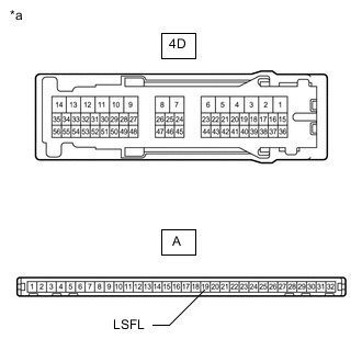
*a Component without harness connected
(Instrument Panel Junction Block Assembly)
Remove the instrument panel junction block assembly.
for LHD:
for RHD:
-
Remove the main body ECU (multiplex network body ECU) from the instrument panel junction block assembly.
for LHD:
for RHD:
-
Measure the resistance according to the value(s) in the table below.
Standard Resistance Tester Connection Condition Specified Condition A-19 (LSFL) - 4D-40 Always Below 1 Ω Result Proceed to OK NG
OK
REPLACE MAIN BODY ECU (MULTIPLEX NETWORK BODY ECU) for LHD: REPLACE MAIN BODY ECU (MULTIPLEX NETWORK BODY ECU) Click here
REPLACE MAIN BODY ECU (MULTIPLEX NETWORK BODY ECU) for RHD: REPLACE MAIN BODY ECU (MULTIPLEX NETWORK BODY ECU) Click hereNG
REPLACE INSTRUMENT PANEL JUNCTION BLOCK ASSEMBLY for LHD: REPLACE INSTRUMENT PANEL JUNCTION BLOCK ASSEMBLY Click here
REPLACE INSTRUMENT PANEL JUNCTION BLOCK ASSEMBLY for RHD: REPLACE INSTRUMENT PANEL JUNCTION BLOCK ASSEMBLY Click here -
-
INSPECT REAR DOOR LOCK ASSEMBLY RH
-
Remove the rear door lock assembly RH.
-
Inspect the rear door lock assembly RH.
Result Proceed to OK NG
NG
REPLACE REAR DOOR LOCK ASSEMBLY RH Click here
OK
-
-
CHECK HARNESS AND CONNECTOR (REAR DOOR LOCK ASSEMBLY RH - MAIN BODY ECU AND BODY GROUND)
-
Disconnect the N3 rear door with motor lock assembly RH connector.
-
Disconnect the I47 main body ECU (multiplex network body ECU) connector.
-
Measure the resistance according to the value(s) in the table below.
Standard Resistance w/ Double Locking System Tester Connection Condition Specified Condition N3-9 (LSSR) - I47-2 (LSWR) Always Below 1 Ω N3-10 (E) - Body ground Always Below 1 Ω N3-9 (LSSR) or I47-2 (LSWR) - Body ground Always 10 kΩ or higher w/o Double Locking System Tester Connection Condition Specified Condition N3-6 (LSSR) - I47-2 (LSWR) Always Below 1 Ω N3-9 (E) - Body ground Always Below 1 Ω N3-6 (LSSR) or I47-2 (LSWR) - Body ground Always 10 kΩ or higher Result Proceed to OK NG
OK
REPLACE MAIN BODY ECU (MULTIPLEX NETWORK BODY ECU) for LHD: REPLACE MAIN BODY ECU (MULTIPLEX NETWORK BODY ECU) Click here
REPLACE MAIN BODY ECU (MULTIPLEX NETWORK BODY ECU) for RHD: REPLACE MAIN BODY ECU (MULTIPLEX NETWORK BODY ECU) Click hereNG
REPAIR OR REPLACE HARNESS OR CONNECTOR
-
-
INSPECT REAR DOOR LOCK ASSEMBLY LH
-
Remove the rear door lock assembly LH.
-
Inspect the rear door lock assembly LH.
Result Proceed to OK NG
NG
REPLACE REAR DOOR LOCK ASSEMBLY LH Click here
OK
-
-
CHECK HARNESS AND CONNECTOR (REAR DOOR LOCK ASSEMBLY LH - INSTRUMENT PANEL JUNCTION BLOCK ASSEMBLY AND BODY GROUND)
-
Disconnect the 4A instrument panel junction block assembly connector.
-
Disconnect the O3 rear door lock assembly LH connector.
-
Measure the resistance according to the value(s) in the table below.
Standard Resistance w/ Double Locking System Tester Connection Condition Specified Condition O3-5 (LSSR) - 4A-34 Always Below 1 Ω O3-6 (E) - Body ground Always Below 1 Ω O3-5 (LSSR) or 4A-34 - Body ground Always 10 kΩ or higher w/o Double Locking System Tester Connection Condition Specified Condition O3-6 (LSSR) - 4A-34 Always Below 1 Ω O3-9 (E) - Body ground Always Below 1 Ω O3-6 (LSSR) or 4A-34 - Body ground Always 10 kΩ or higher Result Proceed to OK NG
NG
REPAIR OR REPLACE HARNESS OR CONNECTOR
OK
-
-
INSPECT INSTRUMENT PANEL JUNCTION BLOCK ASSEMBLY
-
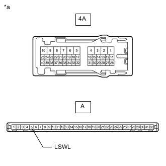
*a Component without harness connected
(Instrument Panel Junction Block Assembly)
Remove the instrument panel junction block assembly.
for LHD:
for RHD:
-
Remove the main body ECU (multiplex network body ECU) from the instrument panel junction block assembly.
for LHD:
for RHD:
-
Measure the resistance according to the value(s) in the table below.
Standard Resistance Tester Connection Condition Specified Condition A-5 (LSWL) - 4A-34 Always Below 1 Ω Result Proceed to OK NG
OK
REPLACE MAIN BODY ECU (MULTIPLEX NETWORK BODY ECU) for LHD: REPLACE MAIN BODY ECU (MULTIPLEX NETWORK BODY ECU) Click here
REPLACE MAIN BODY ECU (MULTIPLEX NETWORK BODY ECU) for RHD: REPLACE MAIN BODY ECU (MULTIPLEX NETWORK BODY ECU) Click hereNG
REPLACE INSTRUMENT PANEL JUNCTION BLOCK ASSEMBLY for LHD: REPLACE INSTRUMENT PANEL JUNCTION BLOCK ASSEMBLY Click here
REPLACE INSTRUMENT PANEL JUNCTION BLOCK ASSEMBLY for RHD: REPLACE INSTRUMENT PANEL JUNCTION BLOCK ASSEMBLY Click here -