AUTOMATIC TRANSAXLE ASSEMBLY INSTALLATION
PROCEDURE
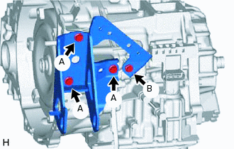
INSTALL TRANSFER AND TRANSAXLE SETTING STUD BOLT
Transfer Side:
Clean the bolt holes.
Apply adhesive 1324 to 2 or 3 threads on one half of a new transfer and transaxle setting stud bolt A as shown in the illustration.
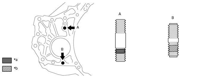
*a
Toyota Genuine Adhesive 1324
*b
Sealant
Adhesive
Toyota Genuine Adhesive 1324, Three Bond 1324 or equivalent
Note:Do not apply adhesive 1324 to the ends of the stud bolt.
Install the stud bolt immediately after applying adhesive to prevent the adherence of foreign matter.
Install the 2 new transfer and transaxle setting stud bolts to the transaxle case positions shown in the illustration.
39.2 N*m
400 kgf*cm
29 ft.*lbf
Note:Install the stud bolt so that the side that has sealant and adhesive is facing the automatic transaxle assembly.
Tip:Stud bolt length:
Stud bolt A: 69 mm (2.72 in.)
Stud bolt B: 47 mm (1.85 in.)
INSTALL TRANSFER ASSEMBLY
INSTALL TORQUE CONVERTER ASSEMBLY
-
Engage the splines of the input shaft and turbine runner.
-
Engage the splines of the stator shaft and the stator while turning the torque converter assembly.
Tip:If the stator shaft splines are difficult to engage with the stator splines, move the torque converter assembly back approximately 10 mm and engage the splines while rotating the torque converter assembly.
-
Turn the torque converter assembly to insert the key of the oil pump drive gear into the groove of the torque converter assembly.
Clean the torque converter assembly set bolt holes.
-
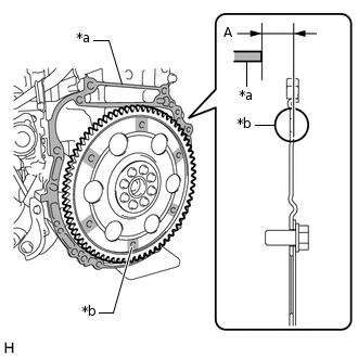
*a
Engine Surface
*b
Drive Plate Surface
Using a vernier caliper and straightedge, measure dimension A between the transaxle contact surface of the engine*a and the torque converter assembly contact surface of the drive plate*b.
Note:Make sure to deduct the thickness of the straightedge.
-
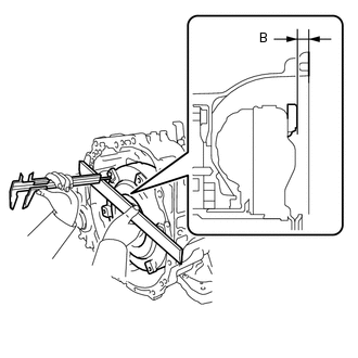
Using a vernier caliper and straightedge, measure dimension B shown in the illustration and check that dimension B is more than dimension A, which was measured in the previous step.
Standard
A + 1 mm (0.0394 in.) or more
Note:Make sure to deduct the thickness of the straightedge.
If the automatic transaxle assembly is installed to the engine with the torque converter assembly not sufficiently inserted, the torque converter assembly may be damaged.
Do not include the thickness of the set block.
-
INSTALL AUTOMATIC TRANSAXLE ASSEMBLY
-
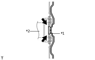
*1
Torque Converter Assembly Centerpiece
*2
Crankshaft
Apply clutch spline grease to the surface of the crankshaft that contacts the torque converter assembly centerpiece.
Clutch spline grease
Toyota Genuine Clutch Spline Grease or equivalent
Maximum grease amount
Approximately 1 g (0.0353 oz.)
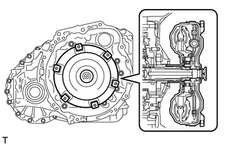
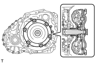
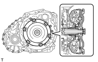
-
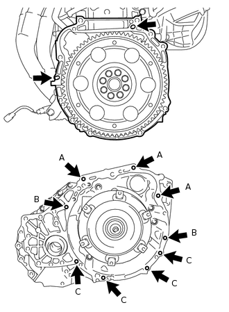
While keeping the engine and automatic transaxle assembly horizontal, align the knock pins with the holes in the automatic transaxle assembly and install the 9 bolts shown in the illustration.
for Bolt A
64 N*m
653 kgf*cm
47 ft.*lbf
for Bolt B
46 N*m
469 kgf*cm
34 ft.*lbf
for Bolt C
44 N*m
449 kgf*cm
32 ft.*lbf
Note:Confirm that the 2 knock pins are installed to the transaxle contact surface of the engine cylinder block before installing the automatic transaxle assembly.
Do not forcibly pry on the automatic transaxle assembly.
Check that the torque converter rotates smoothly after installation of the automatic transaxle assembly.
Tip:Bolt length:
Bolt A: 55 mm (2.17 in.)
Bolt B: 50 mm (1.97 in.)
Bolt C: 33 mm (1.30 in.)
-
INSTALL TRANSMISSION CASE PLUG ASSEMBLY
Apply ATF to a new O-ring and install it to the transmission case plug assembly.
Install the transmission case plug assembly to the automatic transaxle assembly.
INSTALL NO. 1 TRANSMISSION CONTROL CABLE BRACKET
Install the No. 1 transmission control cable bracket to the automatic transaxle assembly with the 2 bolts.
12 N*m
122 kgf*cm
9 ft.*lbf
INSTALL ENGINE MOUNTING BRACKET LH
Clean the bolts and the installation holes in the engine mounting bracket LH.
Apply adhesive to 2 or 3 threads on the ends of the 4 bolts.
Adhesive
Toyota Genuine Adhesive 1324, Three Bond 1324 or equivalent
Install the engine mounting bracket LH to the automatic transaxle assembly with the 4 bolts.
64 N*m
653 kgf*cm
47 ft.*lbf
INSTALL REAR ENGINE MOUNTING BRACKET
Install the rear engine mounting bracket to the automatic transaxle assembly with the 3 bolts.
45 N*m
459 kgf*cm
33 ft.*lbf
INSTALL FRONT ENGINE MOUNTING BRACKET
-
Install the front engine mounting bracket to the automatic transaxle assembly with the 4 bolts.
for Bolt A
64 N*m
653 kgf*cm
47 ft.*lbf
for Bolt B
13.5 N*m
138 kgf*cm
10 ft.*lbf
-
INSTALL TRANSMISSION OIL COOLER
-
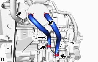
*a
Pink Paint Mark
*b
White Paint Mark
Install the transmission oil cooler to the front engine mounting bracket with the 2 bolts.
13.5 N*m
138 kgf*cm
10 ft.*lbf
Connect the oil cooler inlet hose and oil cooler outlet hose, and slide the clips to secure it.
Note:Make sure that the paint marks are inthe position shown in the illustration.
Make sure that the claws in the illustration are facing toward the front end of the vehicle.
-
INSTALL WIRING HARNESS CONNECTOR
Install the wiring harness connector to the automatic transaxle assembly.
-
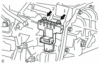
Install and tighten the 2 bolts in the order shown in the illustration.
11.3 N*m
115 kgf*cm
8 ft.*lbf
INSTALL BREATHER HOSE BRACKET
Install the breather hose bracket to the automatic transaxle assembly with the bolt.
20 N*m
204 kgf*cm
15 ft.*lbf
Attach the transmission breather hose sub-assembly to the breather hose bracket.
INSTALL WIRE HARNESS CLAMP BRACKET
Install the 2 wire harness clamp brackets to the automatic transaxle assembly with the 2 bolts.
19.1 N*m
195 kgf*cm
14 ft.*lbf
CONNECT WIRE HARNESS
Attach the 5 wire harness clamps and connect the park/neutral position switch connector.
Connect the connector to the wiring harness connector and turn the lock lever and secure the connector with the lock lever.
Connect the ground cable with the bolt.
19.1 N*m
195 kgf*cm
14 ft.*lbf
INSTALL STARTER ASSEMBLY
for 1.6 kW Type:
for 1.7 kW Type:
INSTALL ENGINE ASSEMBLY WITH TRANSAXLE
INSTALL DRIVE PLATE AND TORQUE CONVERTER ASSEMBLY SETTING BOLT
Remove any adhesive remaining in the 6 bolt holes of the torque converter assembly and 6 drive plate and torque converter assembly setting bolts.
Apply a few drops of adhesive to 2 or 3 threads at the tip of each of the 6 drive plate and torque converter assembly setting bolts.
Adhesive
Toyota Genuine Adhesive 1324, Three Bond 1324 or equivalent
Turn the crankshaft to gain access to the installation locations of the 6 drive plate and torque converter assembly setting bolts and install each bolt while holding the crankshaft pulley with SST.
09213-54015
09330-00021
91551-80650
41 N*m
418 kgf*cm
30 ft.*lbf
Tip:First install the black-colored bolt, and then the remaining 5 silver-colored bolts.
Install the flywheel housing under cover.
CHECK AUTOMATIC TRANSAXLE SYSTEM
Note:If automatic transmission parts have been replaced, refer to the Parts Replacement Compensation Table to determine if any additional operations are necessary.