CHARGING SYSTEM ON-VEHICLE INSPECTION
CAUTION / NOTICE / HINT
If the battery is weak or if the engine is difficult to start, perform the following procedures.
PROCEDURE
CHECK BATTERY CONDITION
Check the battery for damage, deformation and leakage.
If damage, deformation or leakage is found, replace the battery.
Check the electrolyte quantity of each cell.
Tip:Before checking the battery voltage, turn off all the electrical systems (headlights, blower motor, rear defogger, etc.).
If the electrolyte quantity is below the lower line, replace the battery.
If the electrolyte quantity is above the lower line, check the battery voltage when cranking the engine. If the voltage is below 9.6 V, recharge or replace the battery.
Check the voltage.
Turn the ignition switch off and turn on the headlights for 20 to 30 seconds. This will remove the surface charge from the battery.
Measure the voltage according to the value(s) in the table below.
Standard Voltage
Tester Connection
Condition
Specified Condition
Positive (+) terminal - Negative (-) terminal
20°C (68°F)
12.5 to 12.9 V
If the result is not as specified, charge the battery.
CHECK BATTERY TERMINAL AND FUSE
Check that the battery terminals are not loose or corroded.
If the terminals are corroded, clean the terminals.
Positive (+) terminal
5.3 N*m
54 kgf*cm
47 in.*lbf
Negative (-) terminal
5.3 N*m
54 kgf*cm
47 in.*lbf
Measure the resistance of the charging fuses.
Standard resistance
Below 1 Ω
Tip:For fuse locations, refer to Parts Location (Click here).
If the result is not as specified, replace the fuse.
CHECK FAN AND GENERATOR V BELT
VISUALLY CHECK GENERATOR WIRING
Check that the wiring is in good condition.
If the wiring is damaged, repair or replace the generator wire.
LISTEN FOR ABNORMAL NOISE FROM GENERATOR
Check that the generator does not emit any abnormal noise while the engine is running.
If there is abnormal noise, replace the pulley or generator.
CHECK CHARGE WARNING LIGHT CIRCUIT
Turn the ignition switch to ON. Check that the charge warning light turns on.
Start the engine and check that the light turns off.
If the light does not operate as specified, troubleshoot the charge warning light circuit.
CHECK CHARGING CIRCUIT WITHOUT LOAD
-
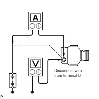
Check the charging circuit.
Put the vehicle in a no-load test condition and run the engine at 2000 rpm. Using a voltmeter and ammeter, measure the battery voltage and current.
Standard current
10 A or less
Standard voltage
12.1 to 15.4 V
If the result is not as specified, replace the generator.
Tip:If the battery is not fully charged, the ammeter reading will sometimes be more than the standard current.
-
CHECK CHARGING CIRCUIT WITH LOAD
Put the vehicle in a load test condition (set the headlights to high beam and set the heater blower switch to Hi) and run the engine at 2000 rpm. Using an ammeter, measure the current.
Check the reading on the ammeter.
Standard current
30 A or higher
If the ammeter reading is below the standard current, replace the generator.
Tip:If the ammeter reading is below the standard current even though the battery is fully charged, the load is not sufficient. Therefore, operate the wiper motor, rear window defogger, etc. to increase the load, and perform the measurement again.
If the battery is fully charged, the ammeter reading will sometimes be below the standard current.
CHECK CHARGING CONTROL SYSTEM
Inspect the wire harness.
w/ Entry and Start System:
Disconnect the H70 power management control ECU connector.
w/o Entry and Start System:
Disconnect the H73 power management control ECU connector.
Disconnect the C101 generator assembly connector.
Measure the resistance according to the value(s) in the table below.
Standard Resistance
Table 1. w/ Entry and Start System Tester Connection
Condition
Specified Condition
H70-1 (LIN1) - C101-1 (LIN)
Always
Below 1 Ω
H70-1 (LIN1) or C101-1 (LIN) - Body ground and other terminals
Ignition switch off (while LIN communication is stopped)
10 kΩ or higher
Table 2. w/o Entry and Start System Tester Connection
Condition
Specified Condition
H73-17 (LIN1) - C101-1 (LIN)
Always
Below 1 Ω
H73-17 (LIN1) or C101-1 (LIN) - Body ground and other terminals
Ignition switch off (while LIN communication is stopped)
10 kΩ or higher