DIFFERENTIAL CARRIER ASSEMBLY DISASSEMBLY

-
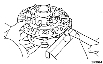
FIX REAR DIFFERENTIAL CARRIER ASSEMBLY
-
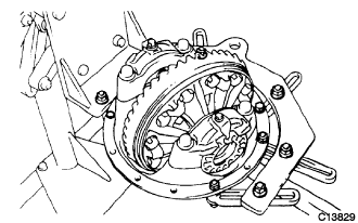
Set the differential carrier to an overhaul stand, etc., as shown in the illustration.
-
-
INSPECT RUNOUT OF REAR DRIVE PINION COMPANION FLANGE SUB-ASSEMBLY
-
Using a dial indicator, measure the runout of the companion flange vertically and horizontally.
Maximum runout 0.10 mm (0.0039 in.) If the runout is greater than the maximum value, replace the companion flange sub-assembly.
-
-
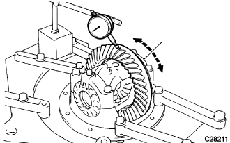
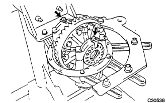
INSPECT RUNOUT OF DIFFERENTIAL RING GEAR
-
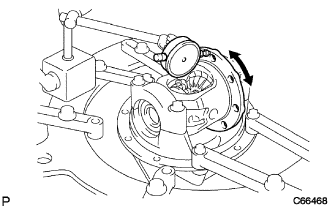
Set the dial indicator perpendicular to the end of the ring gear face.
-
Rotate the ring gear and measure the runout.
Maximum runout 0.07 mm (0.0028 in.) Tech Tips
Measure at a radial position 92 mm (3.62 in.) from the center of the ring gear.
If the runout exceeds the specified maximum value, remove the ring gear and check the runout of the differential case.
-
-
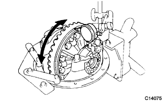
INSPECT DIFFERENTIAL RING GEAR BACKLASH
-
Set the dial indicator perpendicular to the end of the ring gear face.
-
While holding the rear drive pinion companion flange rear, rotate the ring gear and measure the backlash.
Backlash 0.13 to 0.18 mm (0.0051 to 0.0071 in.) Tech Tips
Inspect the backlash at 3 or more locations on the ring gear.
If the backlash is not within the specified range, adjust the preload or repair as necessary.
-
-
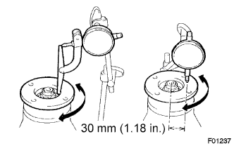
INSPECT DIFFERENTIAL DRIVE PINION PRELOAD
-
Using a socket wrench (30 mm) and torque wrench, measure the preload using the backlash of the drive pinion and ring gear.
Preload (at starting) 0.56 to 0.85 N*m (6.0 to 9.0 kgf*cm, 5.0 to 8.0 in.*lbf)
-
-
INSPECT TOTAL PRELOAD
-
Using a socket wrench (30 mm) and torque wrench, measure the preload with the teeth of the drive pinion and ring gear in contact.
Total preload (at starting) Drive pinion preload plus 0.39 to 0.59 N*m (4.0 to 6.0 kgf*cm, 3.5 to 5.2 in.*lbf)
-
-
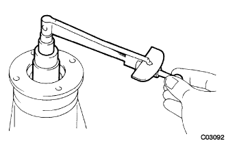
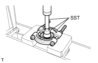
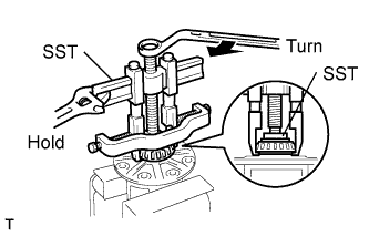
REMOVE REAR DRIVE PINION NUT
-
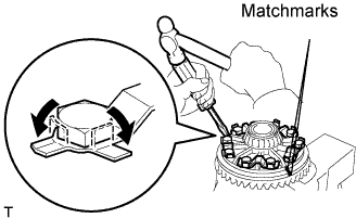
Using SST and a hammer, release the staked part of the drive pinion nut.
- SST
- 09930-00010
Note
-
Be sure to use SST with the tapered surface facing the shaft.
-
Do not grind the tip of SST with a grinder etc.
-
Completely loosen the staked part of the nut when removing it.
-
Do not damage the threads of the drive pinion.
-
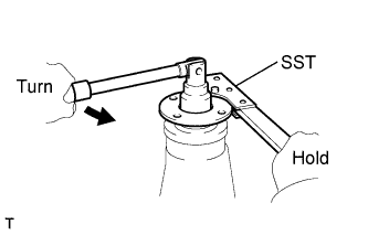
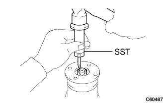
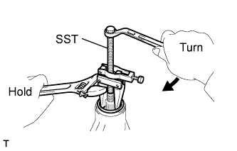
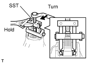
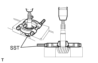
Using SST, hold the flange.
- SST
- 09330-00021
-
Using a socket wrench (30 mm), remove the drive pinion nut.
-
-
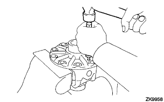
REMOVE REAR DRIVE PINION COMPANION FLANGE SUB-ASSEMBLY
-
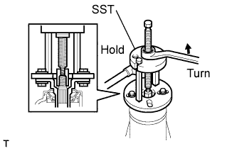
Using SST, remove the companion flange.
- SST
- 09950-30012 ( 09951-03010, 09953-03010, 09954-03010, 09955-03030, 09956-03040 )
Note
Apply grease to the threads and tip of the SST center bolt before use.
-
-
REMOVE REAR DIFFERENTIAL DUST DEFLECTOR
Tech Tips
Perform this procedure only when the dust deflector is damaged.
-
Using SST and a press, remove the dust deflector.
- SST
- 09950-60010 ( 09951-00380 )
- 09950-70010 ( 09951-07150 )
- 09950-00020
-
-
REMOVE REAR DIFFERENTIAL CARRIER OIL SEAL
-
Using SST, remove the oil seal from the differential carrier.
- SST
- 09308-10010
Note
Apply grease to the threads and tip of the SST center bolt before use.
-
-
REMOVE REAR DIFFERENTIAL DRIVE PINION OIL SLINGER
-
REMOVE REAR DRIVE PINION FRONT BEARING
-
Using SST, remove the inner race of the rear drive pinion front tapered roller bearing from the drive pinion.
- SST
- 09556-22010
Note
Apply grease to the threads and tip of the SST center bolt before use.
-
-
REMOVE REAR DIFFERENTIAL BEARING ADJUSTING NUT LOCK
-
Remove the 2 bolts and 2 bearing adjusting nut locks.
-
-
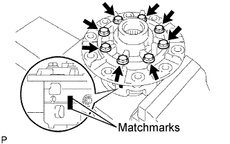
REMOVE DIFFERENTIAL CASE ASSEMBLY
-
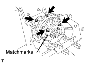
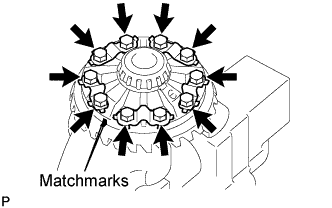
Put matchmarks on either set of the bearing cap and the differential carrier.
-
Remove the 4 bolts and 2 bearing caps.
Note
Do not swap the bearing caps on the carrier as they are manufactured as a set.
-
Remove the 2 rear differential bearing adjusting nuts.
-
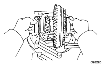
Remove the differential case assembly and case bearing outer races LH and RH from the differential carrier.
-
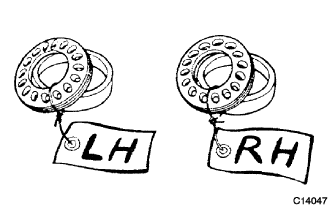
Put identification marks on the case bearing outer races and bearing adjusting nuts to distinguish between the RH side and LH side.
-
-
REMOVE DIFFERENTIAL DRIVE PINION
-
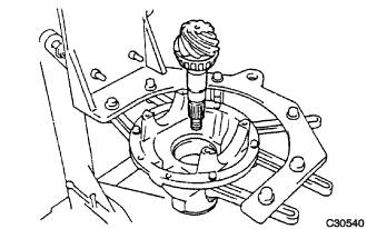
Remove the drive pinion and bearing spacer from the differential carrier.
-
-
REMOVE REAR DRIVE PINION REAR BEARING
-
Using SST and a press, remove the inner race of the rear drive pinion rear tapered roller bearing from the drive pinion.
- SST
- 09950-00020
Tech Tips
If either the drive pinion or ring gear is damaged, replace both as a set.
-
Remove the drive pinion plate washer from the drive pinion.
-
-
REMOVE REAR DRIVE PINION FRONT BEARING
-
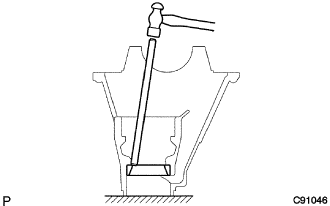
Using a brass bar and a hammer, remove the outer race of the rear drive pinion front tapered roller bearing from the differential carrier.
-
-
REMOVE DIFFERENTIAL OIL STORAGE RING
-
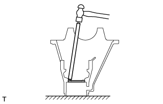
Using a brass bar and a hammer, remove the oil storage ring from the differential carrier.
-
-
REMOVE REAR DRIVE PINION REAR BEARING
-
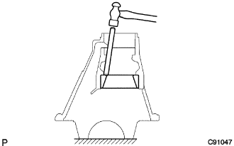
Using a brass bar and a hammer, remove the outer race of the rear drive pinion rear tapered roller bearing from the differential carrier.
-
-
REMOVE DIFFERENTIAL RING GEAR
-
Hold the differential case in a vise between aluminum plates.
Note
Do not overtighten the vise.
-
Put matchmarks on the ring gear and differential case.
-
Using a screwdriver and a hammer, release the 5 lock plates.
-
Remove the 10 ring gear set bolts and 5 lock plates.
-
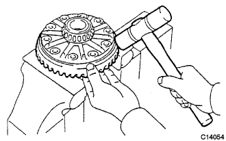
Using a plastic hammer, tap on the ring gear to separate it from the differential case.
Tech Tips
Place a cloth under the toothed surface of the ring gear to prevent damage.
-
-
INSPECT RUNOUT OF DIFFERENTIAL CASE ASSEMBLY
Tech Tips
Perform this procedure only when the runout of the differential ring gear exceeds the specified maximum value.
-
Install the case bearing outer races LH and RH to the case bearing inner races LH and RH respectively.
Note
Be sure to install the bearing outer races in each correct position.
-
Install the differential case to the differential carrier.
-
Align the matchmarks on the bearing cap and differential carrier.
-
Install the right and left bearing caps with the 4 bolts.
- Torque:
- 85 N*m { 870 kgf*cm, 63 ft.*lbf }
-
Using a dial indicator, measure the differential case runout.
Maximum case runout 0.04 mm (0.0016 in.) If the runout is greater than the maximum value, replace the differential case assembly with a new one.
-
Remove the 4 bolts, right and left bearing caps and differential case.
-
-
REMOVE REAR DIFFERENTIAL CASE BEARING
Tech Tips
Perform this procedure only when replacing the case bearing or differential case.
-
Hold the differential case in a vise between aluminum plates.
Note
Do not overtighten the vise.
-
Using SST, remove the case bearing inner race LH and RH from the differential case.
- SST
- 09950-40011 ( 09951-04020, 09952-04010, 09953-04030, 09954-04010, 09955-04061, 09957-04010, 09958-04011 )
- 09950-60010 ( 09951-00360 )
Note
-
Do not deform the bearing cage if the bearing is to be reused.
-
Hook the SST claw from the dent of the differential case to the bearing inner race.
-
Apply grease to the threads and tip of the SST center bolt before use.
-
-
DISASSEMBLE DIFFERENTIAL CASE (2 Pinion Type)
-
Using a pin punch (5 mm) and a hammer, remove the straight pin.
-
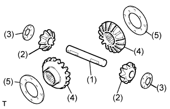
Remove the following parts from the differential case.
(1) Rear differential pinion shaft (2) Rear differential pinion (3) Rear differential pinion thrust washer (4) Rear differential side gear (5) Rear No. 1 differential side gear thrust washer
-
-
DISASSEMBLE DIFFERENTIAL CASE (4 Pinion Type)
-
Place matchmarks on the LH and RH cases.
-
Remove the 8 bolts.
Tech Tips
Loosen the bolts gradually, always skipping to a diagonally opposite bolt.
-
Using a plastic hammer, separate the LH and RH cases.
-
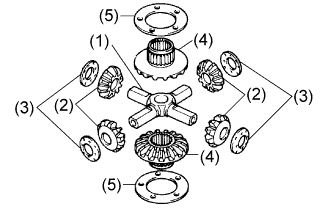
Remove the following parts from the differential case.
(1) Rear differential spider (2) Rear differential pinion (3) Rear differential pinion thrust washer (4) Rear differential side gear (5) Rear No. 1 differential side gear thrust washer
-
-
INSPECT DIFFERENTIAL PINION AND SIDE GEAR
-
Check that there is no damage to the differential pinion gear and side gear.
If the differential pinion gear and/or side gear are damaged, replace them with new ones.
-
-
INSPECT DIFFERENTIAL CASE
-
Check that there is no damage to the differential case. If the differential case is damaged, replace it.
-