ECD SYSTEM, Diagnostic DTC:P0405 and P0406
| DTC Code | DTC Name |
|---|---|
| P0405 | Exhaust Gas Recirculation Sensor "A" Circuit Low |
| P0406 | Exhaust Gas Recirculation Sensor "A" Circuit High |
DESCRIPTION
Refer to DTC P0401.
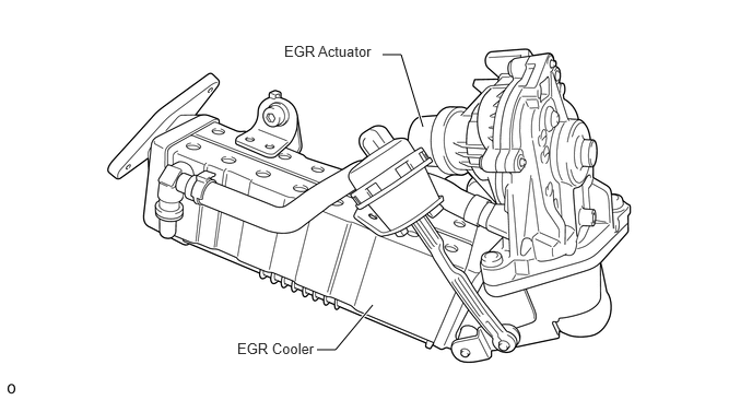
The EGR actuator is electrically opened or closed by the ECM. In order to ensure optimum control of the exhaust gas recirculation rate the ECM must continuously detect the exact position. The position of the EGR actuator is monitored by the EGR valve position sensor.
The DTC motor operates the EGR actuator. The position sensor is a Hall sensor. The Hall sensor detects the revolutions of the servo motor. The position of the EGR actuator is calculated.
The EGR position sensor is installed to the EGR valve assembly and is supplied with 5 V from the ECM.
A bridge circuit (H-bridge) is used to control the servo motor, which allows the servo motor to be operated in the opposite direction. The H-bridge circuit is monitored for diagnosis. An H-bridge electric circuit includes 5 switching elements, which are connected together in the form of the capital letter H.
DTC No. |
Detection Item |
DTC Detection Condition |
Trouble Area |
MIL |
Memory |
|---|---|---|---|---|---|
P0405 |
Exhaust Gas Recirculation Sensor "A" Circuit Low |
EGR valve position sensor output voltage is 0.1 V or less for 0.22 seconds. (3 trip detection logic) |
|
Comes on |
DTC stored |
P0406 |
Exhaust Gas Recirculation Sensor "A" Circuit High |
EGR valve position sensor output voltage is 4.9 V or higher for 0.22 seconds. (3 trip detection logic) |
|
Comes on |
DTC stored |
DTC No. |
Data List |
|---|---|
P0405 P0406 |
|
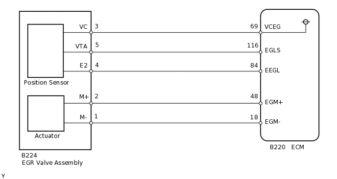
WIRING DIAGRAM
CAUTION / NOTICE / HINT
When replacing the ECM, the ECM needs registration and initialization.
After replacing the EGR valve assembly, the ECM needs initialization.
When the ECM must be replaced, before replacing the ECM, perform the "Learning Values Save" function using the GTS. Then after installing the new ECM, perform all of the initialization/registrations for the "Learning Values Write" function by following the instructions shown on the GTS display.
Read freeze frame data using the GTS. Freeze frame data records the engine condition when malfunctions are detected. When troubleshooting, freeze frame data can help determine if the vehicle was moving or stationary, if the engine was warmed up or not, and other data from the time the malfunction occurred.
PROCEDURE
PERFORM ACTIVE TEST USING GTS (ACTUATOR TEST OF FAN HIGH SPEED AND LOW SPEED)
Connect the GTS to the DLC3.
Turn the ignition switch to ON and turn the GTS on.
Enter the following menus: Powertrain / Engine and ECT / Active Test / Actuator Test of Fan High Speed and Actuator Test of Fan Low Speed.
Powertrain > Engine and ECT > Active Test
Tester Display
Actuator Test of Fan High Speed
Powertrain > Engine and ECT > Active Test
Tester Display
Actuator Test of Fan Low Speed
OK
Cooling fan operates according to operation.
Result
Proceed to
OK
NG
NG REPAIR OR REPLACE COOLING FAN SYSTEMClick here
CHECK HARNESS AND CONNECTOR (EGR VALVE ASSEMBLY - ECM)
Disconnect the EGR valve assembly connector.
Disconnect the ECM connector.
Measure the resistance according to the value(s) in the table below.
Standard Resistance
Tester Connection
Condition
Specified Condition
B224-3 (VC) - B220-69 (VCEG)
Always
Below 1 Ω
B224-5 (VTA) - B220-116 (EGLS)
Always
Below 1 Ω
B224-4 (E2) - B220-84 (EEGL)
Always
Below 1 Ω
B224-3 (VC) or B220-69 (VCEG) - Body ground
Always
10 kΩ or higher
B224-5 (VTA) or B220-116 (EGLS) - Body ground
Always
10 kΩ or higher
B224-4 (E2) or B220-84 (EEGL) - Body ground
Always
10 kΩ or higher
Result
Proceed to
OK
NG
NG REPAIR OR REPLACE HARNESS OR CONNECTORClick here
CHECK HARNESS AND CONNECTOR (VC VOLTAGE)
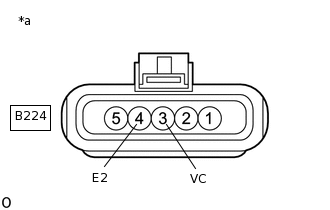
*a
Front view of wire harness connector
(to EGR Valve Assembly)
Disconnect the EGR valve assembly connector.
Turn the ignition switch to ON.
Measure the voltage according to the value(s) in the table below.
Standard Voltage
Tester Connection
Switch Condition
Specified Condition
B224-3 (VC) - B224-4 (E2)
Ignition switch ON
4.5 to 5.5 V
Result
Proceed to
OK
NG
NG REPLACE ECMClick here
REPLACE EGR VALVE ASSEMBLY
Replace the EGR valve assembly.
Perform EGR learning value reset.
Result
Proceed to
NEXT
CHECK WHETHER DTC OUTPUT RECURS (DTC P0405 or P0406)
Connect the GTS to the DLC3.
Turn the ignition switch to ON and turn the GTS on.
Clear the DTCs.
Powertrain > Engine and ECT > Clear DTCs
Turn the ignition switch off and wait for 60 seconds or more [A].
Perform road test [B].
Repeat [A] and [B] for the number of trips detected.
Enter the following menus: Powertrain / Powertrain / Engine and ECT / Trouble Codes.
Powertrain > Engine and ECT > Trouble Codes
Read the DTCs.
Result
Result
Proceed to
No DTC output
A
DTC P0405 or P0406
B
A END
B REPLACE ECMClick here
REPLACE ECM
Replace the ECM.
Result
Proceed to
NEXT
NEXT CONFIRM WHETHER MALFUNCTION HAS BEEN SUCCESSFULLY REPAIREDClick here
REPAIR OR REPLACE HARNESS OR CONNECTOR
Repair or replace the harness or connector.
Result
Proceed to
NEXT
NEXT CONFIRM WHETHER MALFUNCTION HAS BEEN SUCCESSFULLY REPAIREDClick here
REPAIR OR REPLACE COOLING FAN SYSTEM
Repair or replace the cooling fan system.
Result
Proceed to
NEXT
CONFIRM WHETHER MALFUNCTION HAS BEEN SUCCESSFULLY REPAIRED
Connect the GTS to the DLC3.
Turn the ignition switch to ON and turn the GTS on.
Clear the DTCs.
Powertrain > Engine and ECT > Clear DTCs
Turn the ignition switch off and wait for 60 seconds or more [A].
Perform road test [B].
Repeat [A] and [B] for the number of trips detected.
Enter the following menus: Powertrain / Powertrain / Engine and ECT / Trouble Codes.
Powertrain > Engine and ECT > Trouble Codes
Confirm that the DTC is not output again.
Result
Proceed to
NEXT
NEXT END