STABILIZER CONTROL VALVE(w/ KDSS) INSTALLATION
PROCEDURE
INSTALL STABILIZER CONTROL WITH ACCUMULATOR HOUSING ASSEMBLY
Install the stabilizer control with accumulator housing assembly with the 3 bolts.
29 N*m
296 kgf*cm
21 ft.*lbf
Connect the connector, and then attach the clamp to the hole of the bracket.
CONNECT FRONT NO. 1 STABILIZER CONTROL TUBE ASSEMBLY
-
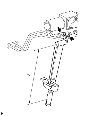
*a
Torque Wrench Fulcrum Length
Temporarily install the 2 flare nuts on the front No. 1 stabilizer control tube assembly.
Using a union nut wrench, tighten the 2 flare nuts on the front No. 1 stabilizer control tube assembly.
Specified tightening torque
44.1 N*m
450 kgf*cm
33 ft.*lbf
Tip:Calculate the torque wrench reading when changing the fulcrum length of the torque wrench.
When using a union nut wrench (fulcrum length of 30 mm (1.1811 in.)) + torque wrench (fulcrum length of 380 mm (14.9606 in.)): 40.9 N*m (417 kgf*cm, 30 ft.*lbf)
-
CONNECT REAR NO. 1 STABILIZER CONTROL TUBE ASSEMBLY
-
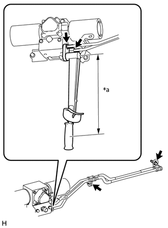
*a
Torque Wrench Fulcrum Length
Temporarily install the 2 flare nuts on the rear No. 1 stabilizer control tube assembly.
Connect the rear No. 1 stabilizer control tube assembly with the 2 bolts.
29 N*m
296 kgf*cm
21 ft.*lbf
Using a union nut wrench, tighten the 2 flare nuts on the rear stabilizer control tubes.
Specified tightening torque
44.1 N*m
450 kgf*cm
33 ft.*lbf
Tip:Calculate the torque wrench reading when changing the fulcrum length of the torque wrench.
When using a union nut wrench (fulcrum length of 30 mm (1.1811 in.)) + torque wrench (fulcrum length of 380 mm (14.9606 in.)): 40.9 N*m (417 kgf*cm, 30 ft.*lbf)
-
BLEED AIR FROM SUSPENSION FLUID
APPLY PRESSURE ACCORDING TO TEMPERATURE MANAGEMENT CHART WHEN FILLING FLUID
INSPECT FOR SUSPENSION FLUID LEAK
MEASURE VEHICLE HEIGHT
INSTALL STABILIZER CONTROL VALVE PROTECTOR
Install the stabilizer control valve protector with the 2 bolts.
29 N*m
296 kgf*cm
21 ft.*lbf
INSTALL SIDE STEP ASSEMBLY LH
CONNECT CABLE TO NEGATIVE BATTERY TERMINAL
Note:When disconnecting the cable, some systems need to be initialized after the cable is reconnected (Click here).